
Guide electromagnetic valve with hand push button

A pilot-operated solenoid valve and pilot-operated valve technology, which is applied to flushing equipment with water tanks, valve devices, valve details, etc., can solve the problems of solenoid valve failure, no filter, and many consumables, so as to save materials and prevent The effect of long service life and small size

Inactive Publication Date: 2009-03-25
宁波中车时代电气设备有限公司
View PDF0 Cites 9 Cited by
  • Summary
  • Abstract
  • Description
  • Claims
  • Application Information

AI Technical Summary

Problems solved by technology

[0002] The electromagnetic water valve used in the existing squatting toilet induction flusher adopts a diaphragm structure without a water cut-off mechanism. If the electromagnetic valve is repaired, the main water supply valve must be closed before proceeding, which is very inconvenient and also Without a filter, if it is added with a filter and a stop valve, the volume of the whole product is relatively large and there are many consumables
Moreover, when the current solenoid valve is used in automatic flushing occasions, its manual function is triggered electronically. If there is no electricity, both the solenoid valve and the manual operation function will be useless.

Method used


Image

  • Guide electromagnetic valve with hand push button
  • Guide electromagnetic valve with hand push button
  • Guide electromagnetic valve with hand push button

Examples


Embodiment Construction

[0021] The present invention will be further described in detail below in conjunction with the accompanying drawings and embodiments.

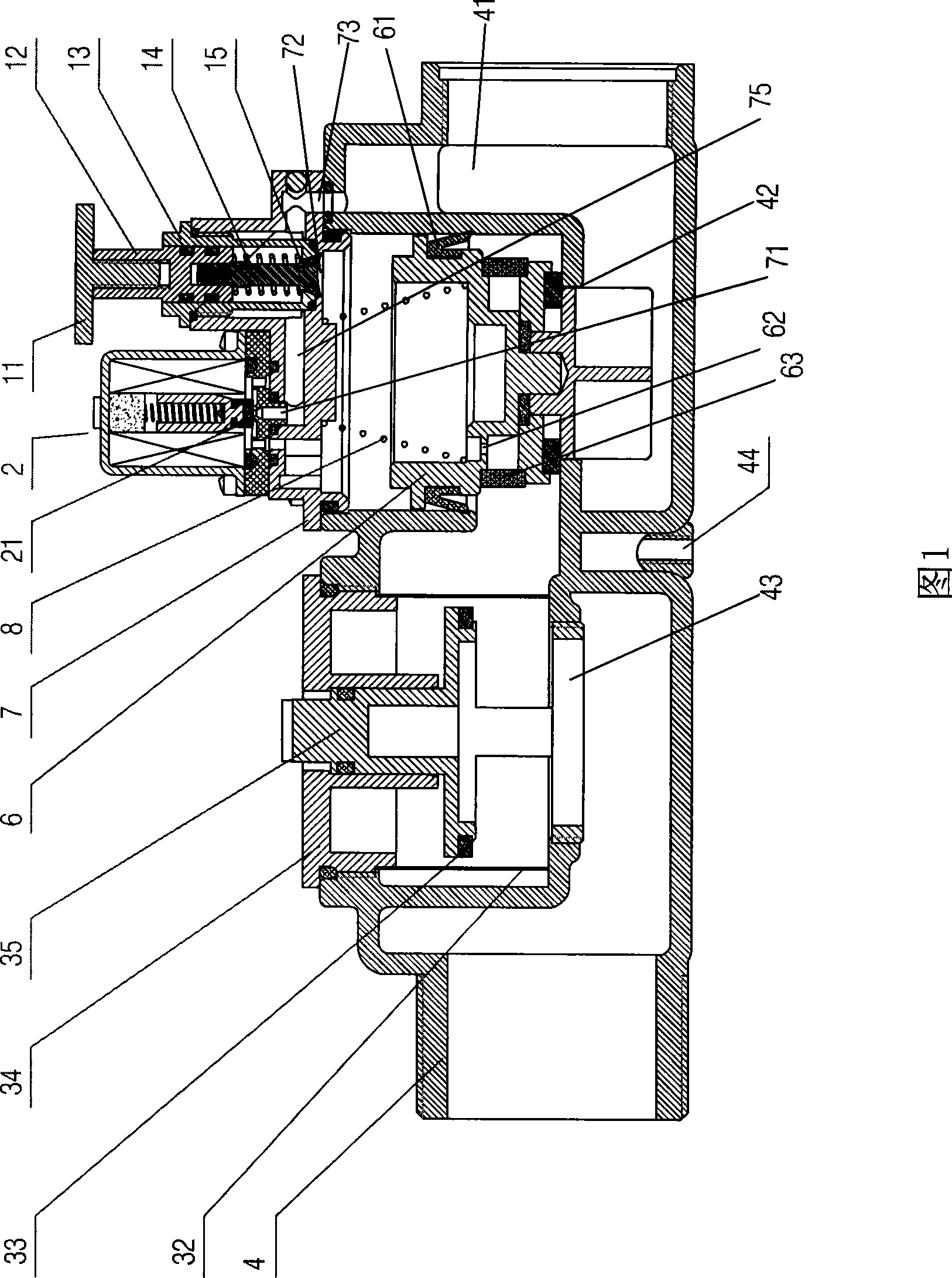
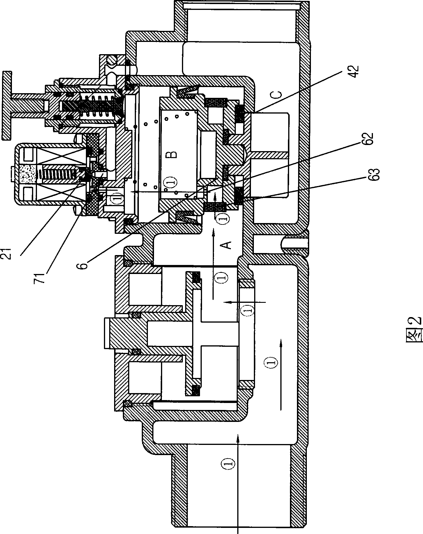
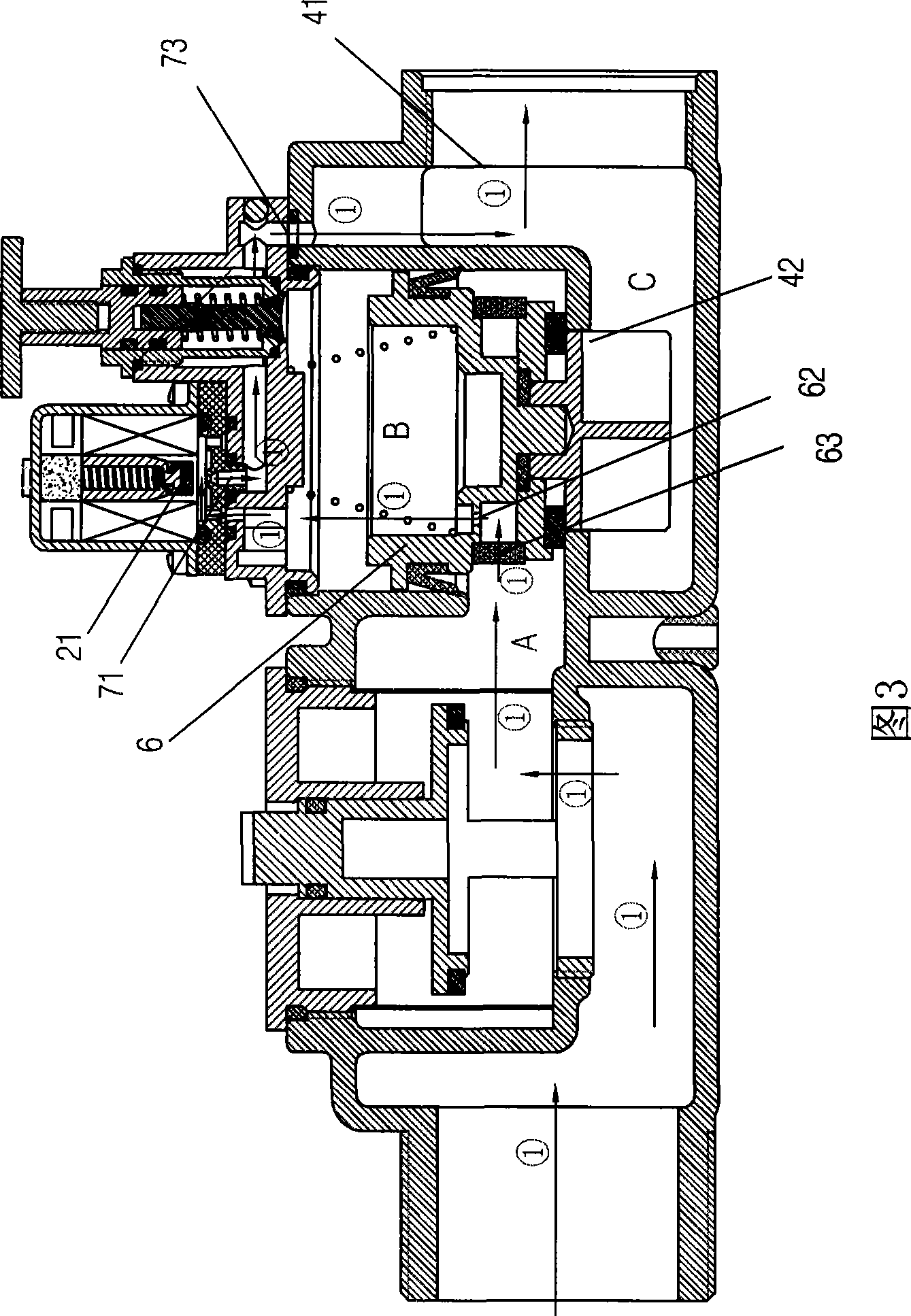
[0022] As shown in Figure 1 and Figure 6, the pilot solenoid valve with manual button includes the main valve body 4, the cut-off filter valve assembly 3, the movable spool assembly 6, the return spring 8, the pilot valve body 7, the solenoid valve assembly 2 and The manual valve assembly 1, the cut-off filter valve assembly 3 is arranged on the front passage in the main valve body 4, the rear passage in the main valve body 4 is divided into upper and lower two passages, the entrance of the upper passage is provided with a movable spool assembly 6 with a small hole 62, and the upper passage The outlet valve body is connected to the pilot valve body 7, and a sealed cavity is formed between the movable valve core assembly 6 and the pilot valve body 7, and one end of the return spring 8 is supported on the pilot valve body 7, and the other end is ...


PUM


Abstract

The invention discloses a leading type electromagnetic valve with a hand-operated button, which comprises a main valve body, a check filter valve component, a movable valve core component, a return spring, a leading valve body component, an electromagnetic valve and a hand-operated valve. The check filter valve component is arranged on a front passage inside the main valve body. A back passage inside the main valve body is divided into an upper passage and a lower passage, the movable valve core component with an eyehole is arranged at an inlet of the upper passage, the valve body at an outlet of the upper passage is connected with the leading valve body, and a seal cavity is formed between the movable valve core component and the leading valve body. One end of the return spring is supported on the leading valve body, and the other end of the return spring is supported on the movable valve core component capable of sealing or opening an inlet of the lower passage. A front inlet and a back inlet arranged on a passage of the leading valve body are both connected with the passage of the main valve body, an outlet of the passage of the leading valve body is connected with the outlet end of the main valve body, the electromagnetic valve is arranged on the passage of the leading valve body, the hand-operated valve is arranged on the back inlet of the passage of the leading valve body, and an outlet of the lower passage is connected with the outlet end of the main valve body. The leading type electromagnetic valve has the advantages of convenient maintenance and repair, compact structure, small volume and raw material conservation. The normal use of the valve can be controlled even during power failures.

Description

technical field [0001] The invention relates to a pilot electromagnetic valve, in particular to an electromagnetic water valve used for a squat urinal induction flusher among induction sanitary ware. Background technique [0002] The electromagnetic water valve used in the existing squatting toilet induction flusher adopts a diaphragm structure without a water cut-off mechanism. If the electromagnetic valve is repaired, the main water supply valve must be closed before proceeding, which is very inconvenient and also Without a filter, if it is added with a filter and a stop valve, the volume of the whole product is relatively large and there are many consumables. And when the present electromagnetic valve is applied to the occasion of automatic flushing, its manual function relies on electronic triggering, if there is no electricity, then the electromagnetic valve and the manual operation function all lose their effect. Contents of the invention [0003] The technical prob...

Claims


Application Information

Patent Timeline
Patent Type & Authority Applications(China)
IPC IPC(8): E03D5/10F16K31/06F16K31/44
Inventor 肖国彬
Owner 宁波中车时代电气设备有限公司
Learn More