Warp knitting machine pattern bar traversing device

A technology of traversing device and machine flower, applied in the field of warp knitting machines, can solve the problems of missing needles, increased production costs, insufficient movement of yarn guide needles, etc.

Active Publication Date: 2009-03-25
CHANGZHOU RUNYUAN WARP KNITTING MACHINERY
View PDF1 Cites 6 Cited by
  • Summary
  • Abstract
  • Description
  • Claims
  • Application Information

AI Technical Summary

Problems solved by technology

[0002] Existing warp knitting machine flower comb traverse device mainly contains two kinds, one kind mainly is made of bar seat, bar, guide rail, guide needle and limit device, and guide needle is installed on the bar, and bar passes A number of short guide rails are installed on the comb seat, and the upper and lower sides of the guide rail are respectively equipped with arc-shaped convex slide rails, and the comb bars corresponding to the slide rails are provided with arc-shaped groove-type chutes, and the comb bars pass through the chute. Clamped between the guide rails by the slide rails, when the comb bars move laterally from side to side, the comb bars slide on the arc-shaped convex slide rails of the guide rails through their chute; The length of the entire guide rail formed by installing several short guide rails on the bar seat is relatively long, generally 2 to 3 meters, so the slender bar and the chute on it must be manufactured and installed. It is very difficult to be completely straight, and there are unevenness in some places; similarly, it is very difficult to be completely straight for the whole slide rail composed of several short slide rails, and there are also unevenness in some places. Therefore, when the bar is moving laterally, the sticking phenomenon often occurs, especially when the unevenness of the chute and the slide rail is superimposed and under the action of factors such as dust, the degree of sticking is more serious, or even stuck, so that Cause the yarn guide needle to not move in place, seriously affecting the adverse consequences of fabric quality
In addition, the limiting device includes a boss located at the lower end of the bar seat, and the boss and the bar seat are integrally made, and the raw materials consumed when manufacturing such a bar seat with a boss are relatively small. more, and the processing is more difficult, which increases the production cost
Another structure of the patterned comb traverse device, in order to overcome the above-mentioned stuck phenomenon in the prior art, the arc-shaped boss-type slide rail on the above-mentioned guide rail is replaced by balls, but the structure of this guide rail is complicated. It is difficult to manufacture and the cost is high, and in the process of use, because the cover plate that seals the balls is often detached, the balls leak out, causing the bar to move up and down during the lateral movement, resulting in the movement of the guide needle not in place, injection, injection, etc. The phenomenon of missing needles occurs from time to time; the patterned comb traverse device of this structure has been described in detail in the Chinese utility model patent, the patent number is 200620070149.8, and the title is a device for comb traverse.

Method used


Image

  • Warp knitting machine pattern bar traversing device
  • Warp knitting machine pattern bar traversing device
  • Warp knitting machine pattern bar traversing device

Examples


Embodiment Construction

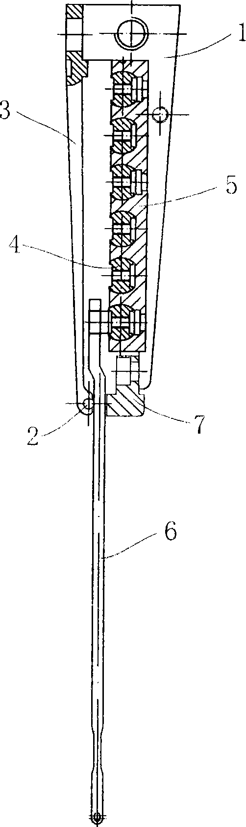
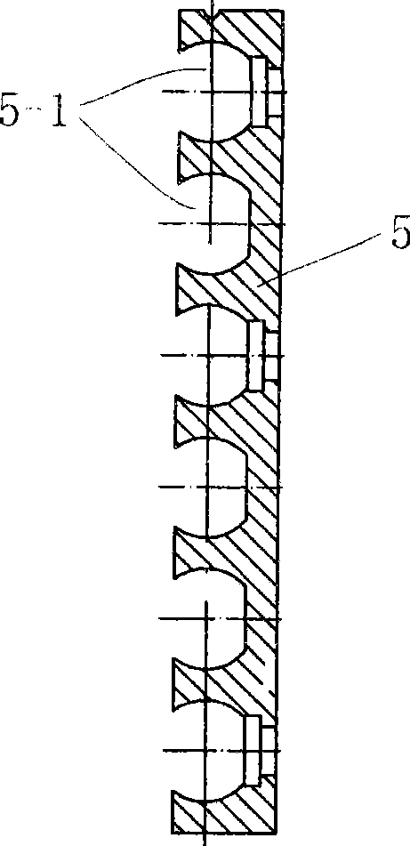
[0019] see Figure 1 to Figure 9 The shown warp knitting machine flower comb traverse device includes a bar seat 1, one end is fixedly connected with the bar seat 1 by a bolt, and the other end passes through a cover plate 3 and a bar 4 for clamping and retaining the needle steel wire 2. Install the guide rail 5 of the comb bar 4 and the yarn guide needle 6 installed on the comb bar 4, the guide rail 5 is fixed on the comb bar seat 1 by a plurality of bolts at a distance from each other in the longitudinal direction, The comb bar 4 is a chamfered cylinder with at least one side chamfered along its axis, and a groove 5-1 which is too small and whose shape matches the chamfered cylinder is provided on the guide rail 5 .

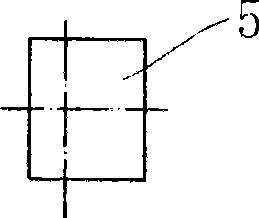
[0020] See Figure 4 to Image 6 , the comb bar 4 is a chamfered cylinder along both sides of its axis, and a guide groove 4-1 for installing the guide needle 6 is provided on at least one side of the chamfered plane, and along the The guide grooves 4-1 are sp...


PUM


Abstract

The invention discloses a pattern-combing traversing device of a warp knitting machine, which includes a bar holder, a covering plate with one end fixedly connected with the bar holder and the other end passing and clamping the wires of a baffling needle, a bar, a guide rail used for arranging the bar and a yarn guide needle arranged on the bar; the guide rails are longitudinally and fixedly arranged on the bar holder with certain space, the bar is a chamfered cylinder with at least one chamfered side along the axis, the guide rail is provided with a groove which matches with the chamfered cylinder in size and shape; the bar can be a chamfered cylinder with chamfered edge at two symmetrical sides along the axis, also a guiding groove for installing the yarn guide needle is arranged on the chamfered plane at both sides and mounting holes with certain space are arranged along the guiding groove. The invention can effectively overcome clamping stagnation and dead clamp when the bar makes transverse movement in the guide rail, and guarantee that the movement of the yarn guide needle is accurate; also the invention is simple in structure and convenient for installation and repair and can be generalized on the warp knitting machine.

Description

technical field [0001] The invention relates to a warp knitting machine with at least one patterned bar, in particular to a patterned comb traverse device on the warp knitting machine. Background technique [0002] Existing warp knitting machine flower comb traverse device mainly contains two kinds, one kind mainly is made of bar seat, bar, guide rail, guide needle and limit device, and guide needle is installed on the bar, and bar passes A number of short guide rails are installed on the comb seat, and the upper and lower sides of the guide rail are respectively equipped with arc-shaped convex slide rails, and the comb bars corresponding to the slide rails are provided with arc-shaped groove-type chutes, and the comb bars pass through the chute. Clamped between the guide rails by the slide rails, when the comb bars move laterally from side to side, the comb bars slide on the arc-shaped convex slide rails of the guide rails through their chute; The length of the entire guid...

Claims


Application Information

Patent Timeline
Patent Type & Authority Applications(China)
IPC IPC(8): D04B27/26
Inventor 王占洪刘莉萍朱晓宏徐敏平
Owner CHANGZHOU RUNYUAN WARP KNITTING MACHINERY
Why Eureka
Try Eureka