Target shape detecting method and device
A target shape, to-be-detected technology, applied in image data processing, instrument, character and pattern recognition, etc., can solve problems such as low algorithm operation efficiency, increased false detection, and confusion, and achieve stable efficiency, robustness, and high efficiency. and robustness effects
- Summary
- Abstract
- Description
- Claims
- Application Information
AI Technical Summary
Problems solved by technology
Method used
Image
Examples
no. 1 example ( 3
[0028] First Embodiment (Triangle Detection and Tracking)
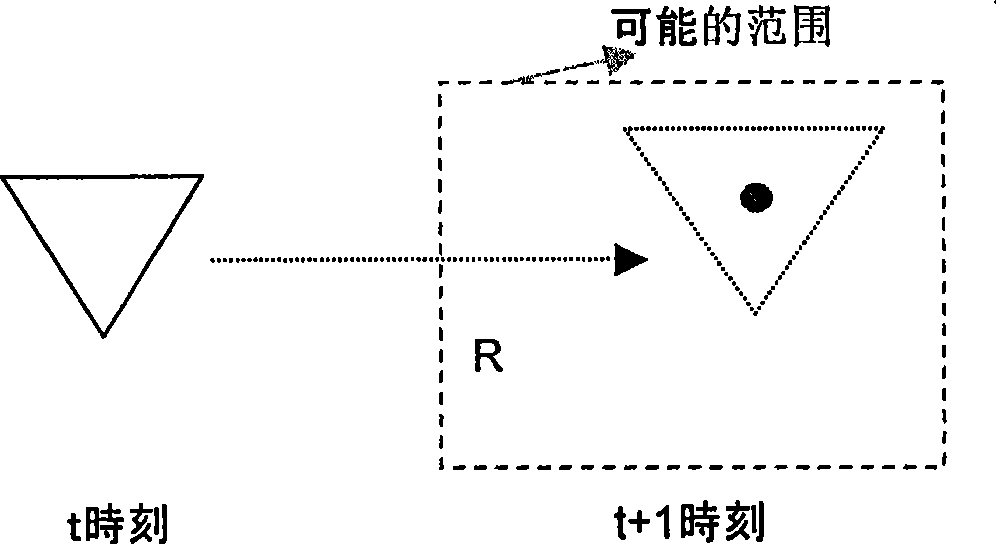
[0029] In order to facilitate the understanding of the present invention, a regular triangle is taken as an example to describe the process of detecting and tracking a regular triangle. For simplicity, it can be assumed that the base of the equilateral triangle is above and horizontal. Figures 2a to 2d It shows the process of detecting and tracking the equilateral triangle target at time t and t+1.
[0030] It can be assumed that the target position of the equilateral triangle to be detected in the current frame of the image at a given time t is p t (x, y), the possible position of the target in the frame at time t+1 is located in a w×h rectangular box R. Where w represents the width of the rectangular box R, and h represents the height of the rectangular box R. The rectangular box R only needs to give the approximate area where the target may appear, and does not require an explicit motion model or calculation of...
no. 2 example
[0046] The second embodiment (quadrangle detection)
[0047] The process of detecting the shape of a quadrilateral is described below by taking a quadrilateral as an example. For the sake of simplicity, the description of the same part as the triangle detection and tracking method is omitted here, and only the differences from the triangle-shaped target tracking method are described.
[0048] Figure 4 A schematic diagram showing the continuation direction for continuation of a regular quadrilateral target shape. The sampling points in the quadrilateral target shape detection process can have four extension directions. The four continuation directions can be perpendicular to the four sides that make up the quadrilateral. Without loss of generality, it can be assumed that the angles of the four sides of the target quadrilateral are θ 1 , θ 2 , θ 3 , θ 4 , then the continuation direction angle of the sampling point is θ 1 -90, theta 2 -90, theta 3 -90, theta 4 -90. T...
no. 3 example
[0050] The third embodiment (circle detection)
[0051] Refer below Figure 5a with 5b A detection and tracking method for objects with circular outlines is described. For a circle, if each sampling point is extended in the vertical direction, the directions of the candidate sides of the edge points generated by the sampling points are different due to the different positions of the sampling points.
[0052] For circular targets, each sampling point can be fixed along 4 continuation directions. For the convenience of calculation, four extension directions of 0, 90, 180, and 270 degrees are usually selected, as shown in Fig. 5(a). It should be noted that the present invention is not limited thereto, and each sampling point may also extend along 8 directions or 16 directions. In the case of extension along eight directions, the extension directions can be 0, 45, 90, 135, 180, 225, 270, and 315 degrees, as shown in Fig. 5(b). Similarly, if the continuation is carried out alo...
PUM
 Abstract
Description
Claims
Application Information
 - R&D
- Intellectual Property
- Life Sciences
- Materials
- Tech Scout
- Unparalleled Data Quality
- Higher Quality Content
- 60% Fewer Hallucinations
Browse by: Latest US Patents, China's latest patents, Technical Efficacy Thesaurus, Application Domain, Technology Topic, Popular Technical Reports.
© 2025 PatSnap. All rights reserved.Legal|Privacy policy|Modern Slavery Act Transparency Statement|Sitemap|About US| Contact US: help@patsnap.com


