
Screen

A screen and main body technology, applied in optics, instruments, projection devices, etc., can solve the problems of wall collision, screen main body placed opposite, and ineffective use of space, etc., to achieve a stable supporting state and good utilization effects

Inactive Publication Date: 2009-03-18
SEIKO EPSON CORP
View PDF1 Cites 1 Cited by
  • Summary
  • Abstract
  • Description
  • Claims
  • Application Information

AI Technical Summary

Problems solved by technology

Therefore, when the screen main body is arranged and used close to the wall, at least one of the three legs will collide with the wall, and it is difficult to place the screen main body at a desired close position relative to the wall, and there is no effective issues such as efficient use of space

Method used


Image

  • Screen
  • Screen
  • Screen

Examples


Embodiment Construction

[0048] (Schematic structure of the screen)

[0049] One embodiment of the present invention will be described below with reference to the drawings.

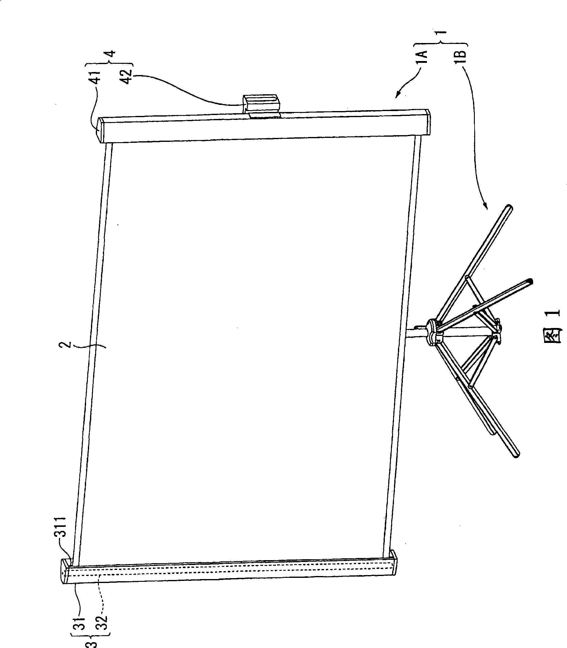
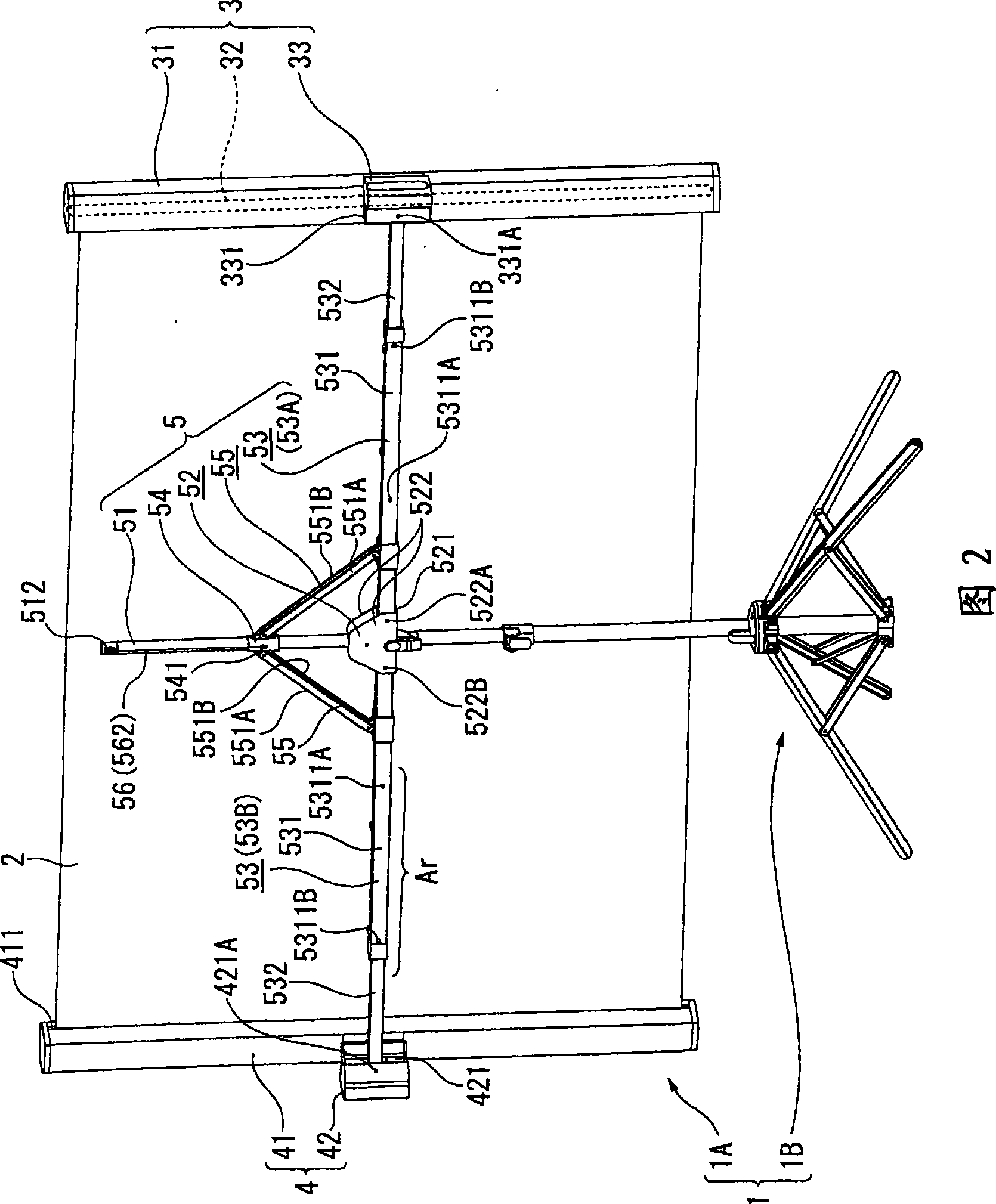
[0050] 1 and 2 are perspective views showing a schematic configuration of the screen 1 . Specifically, FIG. 1 is a perspective view of the screen 1 viewed from the front side where image light is incident. FIG. 2 is a perspective view of the screen 1 viewed from the rear side.

[0051] In addition, "left" and "right" described below represent left and right when viewed from the rear side of the screen 1 .

[0052] On the screen 1, for example, image light enlarged and projected from a projector or the like is projected. As shown in FIG. 1 or FIG. 2, the screen 1 is roughly composed of an image projection part 1A, a support leg 1B, a binding member 1C (refer to Figure 13 )constitute.

[0053] (Structure of Image Projector)

[0054] The image projection unit 1A is a portion for projecting image light, and as shown in FIG. 1 ...


PUM


Abstract

The invention provides a screen for effectively utilizing space. A support leg (1B) comprises: a a support leg body (6) shaped substantially like a pillar, four leg sections (7) that support upright the support leg body (6) by abutting, at each one end, a placement surface, and a connection member (8) that is attached to the support leg body (6) and connects together the other end of each of the leg sections and the support leg body. The connection member (8) pivotally supports the other end of at least any of the leg sections (7) about a shaft substantially parallel to a vertical shaft. Through causing each leg sections (7) to rotate relative the connection member (8) using a shaft parallel with the vertical shaft as a center, the angle formed between each leg sections (7) using the support leg body (6) as the center is properly changed.

Description

technical field [0001] The invention relates to a screen. Background technique [0002] Conventionally, a screen is known that includes an image projection unit having a screen main body for projecting an enlarged image projected from a projector or the like, and support legs for supporting the image projection unit (for example, refer to Patent Document 1). [0003] The support leg described in Patent Document 1 is configured such that an image projection unit is attached to a raised support supported by three leg portions to support the entire screen. [0004] Patent Document 1: Japanese Utility Model Registration No. 3040235 [0005] However, in the screen described in Patent Document 1, the three leg portions are all arranged at predetermined angles in the rotational direction around the pillar. Therefore, when the screen main body is arranged and used close to the wall, at least one of the three legs will collide with the wall, and it is difficult to place the screen ...

Claims


Application Information

Patent Timeline
Patent Type & Authority Applications(China)
IPC IPC(8): G03B21/56G03B21/58
CPCF16M11/046F16M11/041F16M11/38F16M11/045F16M11/18G03B21/58F16M11/34F16M11/245
Inventor 吉野泰德盐原忍丸山昌人
Owner SEIKO EPSON CORP
Learn More