
Solar steam generator

A solar steam and generator technology, applied in steam generation, solar thermal power generation, steam generation methods, etc., can solve the problems of low production efficiency, complicated production process of mirrors, and difficult to clean.

Inactive Publication Date: 2009-03-18
陈应天
View PDF0 Cites 5 Cited by
  • Summary
  • Abstract
  • Description
  • Claims
  • Application Information

AI Technical Summary

Problems solved by technology

[0003] The defect of the former device is: when in use, once the dust enters the narrow gap of the Fresnel lens, it is difficult to clean it off, which will seriously reduce the light transmittance, and it is difficult to maintain, and the cost of the solar steam generator is relatively high. more expensive;
[0004] The defect of the latter device is: the production process of the large-caliber parabolic cylindrical reflector is complicated, the production efficiency is low, and the cost is high. In addition, the mirror surface of the reflector is not axially symmetrical, so even if the mirror surface is divided into Several individual mirrors with the same optical axis have different calibers and must be produced separately, which is more costly and difficult to assemble
Therefore, there are high requirements for the shape and optical precision of the mirror surface, which makes the manufacturing process of the mirror complicated, so that the manufacturing cost of the corresponding solar steam generator is relatively high;
[0005] In addition, both devices are high-power concentrators. Although they can achieve a good concentrating effect (the geometric concentrating ratio is 20 to 80 times), the light they gather has uneven distribution of light intensity, and due to the Blocking, there is a blind spot in the central area of ​​the light-receiving side of the heat-absorbing plate where the sun’s rays cannot be concentrated, so that the heat-absorbing plate is heated unevenly
[0006] The existence of the above-mentioned defects makes the existing solar steam generators unable to be used in large-scale industrialization

Method used


Image

  • Solar steam generator
  • Solar steam generator
  • Solar steam generator

Examples


Embodiment Construction

[0017] Embodiments of the present invention will be specifically described below in conjunction with the accompanying drawings:

[0018] See Figure 1— Figure 4 :

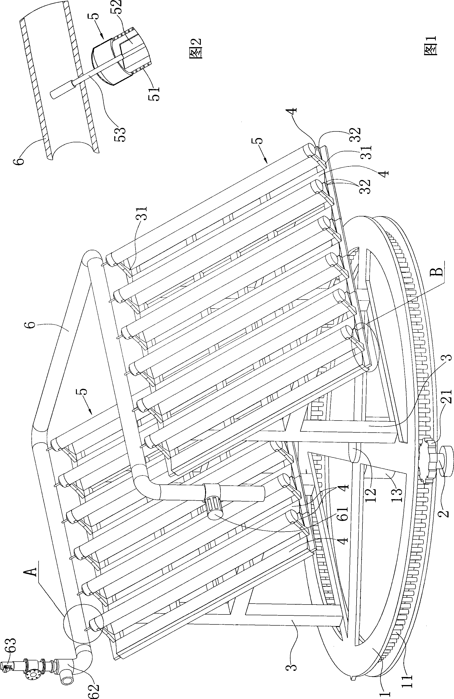
[0019] The solar steam generator includes a circular rotating platform 1 that can track the sun in azimuth, a pin-tooth motor, two support frames 3 that are arranged front and back on the rotating platform 1 and can adjust the elevation angle, and twelve inclined Solar collector tube 5, twenty-four inclined mirrors 4, the pipeline 6 through which water is supplied, do not show the pin-tooth motor in the accompanying drawings, only show its output shaft 2 and the drive gear 21 on the output shaft 2.

[0020] Every six solar heat collection tubes 5 are arranged parallel to each other above a support frame 3, and each solar heat collection tube 5 is connected to the corresponding support frame 3 through two decks 31 arranged up and down, and the rotating platform 1 passes through its center. The provided downward ex...


PUM


Abstract

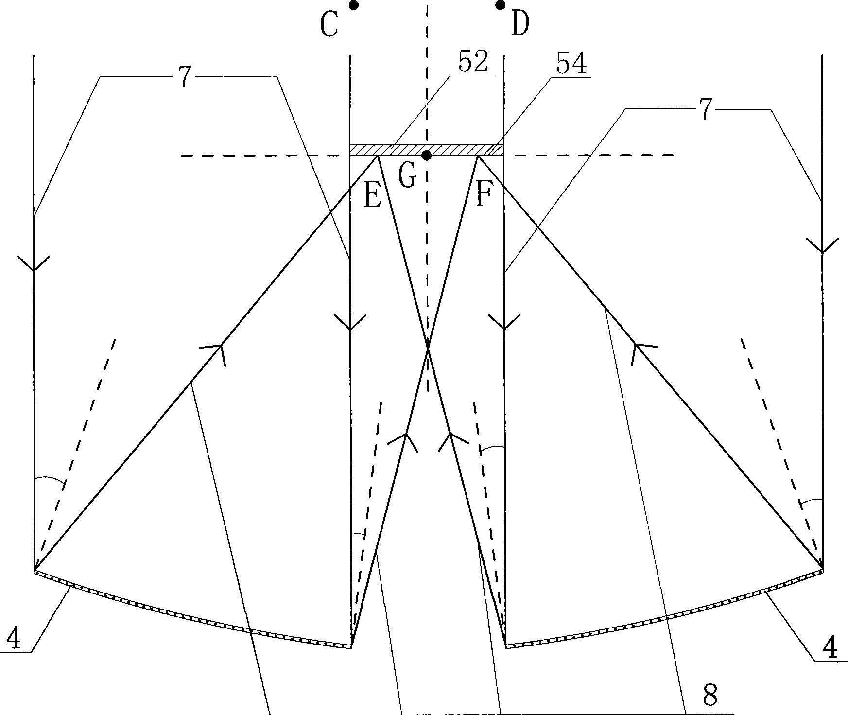
The invention relates to a solar steam generator. The solar steam generator at least comprises a supporting rack and a plurality of oblique solar heat collecting tubes which are arranged on the upper part of the supporting rack in parallel; each solar heat collecting tube comprises a glass vacuum tube, a strip heat absorption plate and a thermotube with two closed ends and a working medium inside; the upper heat exchange end of the thermotube is positioned outside the glass vacuum tube and extends into a pipeline so that the upper end of the solar heat collecting tube is provided with the pipeline for fluid to pass through; the supporting rack corresponding to each glass vacuum tube is provided with a plurality of reflecting mirrors arranged along the length direction of the glass vacuum tube in order that solar rays are converged on the corresponding light interception side of the heat absorption plate which is close to the supporting rack; the reflecting mirrors are symmetrically positioned on two sides of the glass vacuum tube and have different optical shafts; and the mirror face of the reflecting mirror can be a plane, a cylindrical surface, a parabolic cylindrical surface, the combination of the formers and any of combinations of two of the formers. The solar steam generator has low cost and can be used for large-scale industrialization.

Description

technical field [0001] The invention relates to a solar steam generator. Background technique [0002] At present, there is an existing solar steam generator, which at least includes a support frame, several inclined solar heat collection tubes arranged parallel to each other above the support frame, and pipelines for fluid passage. The solar heat collection tubes include glass vacuum tubes, strip-shaped Heat-absorbing plate, heat pipe with both ends closed and working medium inside, the heat pipe is arranged along the length direction of the heat-absorbing plate and connected with the plate in close contact, the heat-absorbing plate and the lower heat-absorbing section of the heat pipe are sealed and placed in a glass vacuum tube , the upper heat exchange end of the heat pipe is located outside the glass vacuum tube and extends into the pipeline, so that there is a pipeline at the upper end of the solar heat collection tube, and a light concentrating device is installed on ...

Claims


Application Information

Patent Timeline
IPC IPC(8): F22B1/00F24J2/32F24J2/05F24J2/10F24J2/38F24S10/40F24S10/95F24S23/70F24S50/20
CPCY02E10/47Y02E10/44Y02P80/20
Inventor 陈应天
Owner 陈应天
Learn More