
Internal circlip press-loading device

A technology of press-fitting device and inner circlip, which is applied in the direction of electromechanical devices, manufacturing motor generators, electrical components, etc., can solve the problems of inconvenient operation, lack of auxiliary guidance, and inability to pre-press workpieces, etc., to achieve convenient operation and guiding good sex effect

Inactive Publication Date: 2009-03-18
ZHEJIANG LINIX MOTOR
View PDF1 Cites 67 Cited by
  • Summary
  • Abstract
  • Description
  • Claims
  • Application Information

AI Technical Summary

Problems solved by technology

[0005] The object of the present invention is to provide a kind of inner circlip pressing device with good guiding ability, which can ensure the smooth assembly of the circlip and is easy to operate, which solves the lack of auxiliary guidance existing in the existing circlip pressing tooling, which is easy to cause The snap ring (equivalent to the snap ring) deviates from the workpiece that needs to be assembled with the snap ring, so the snap ring cannot be smoothly assembled into the workpiece, the workpiece cannot be pre-loaded, and there are problems such as inconvenience in operation.

Method used


Image

  • Internal circlip press-loading device
  • Internal circlip press-loading device
  • Internal circlip press-loading device

Examples


Embodiment 1

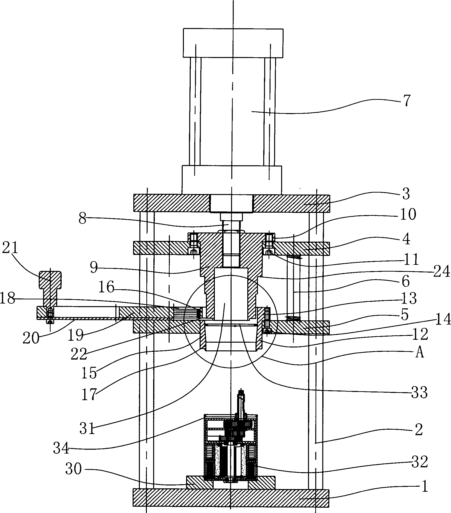
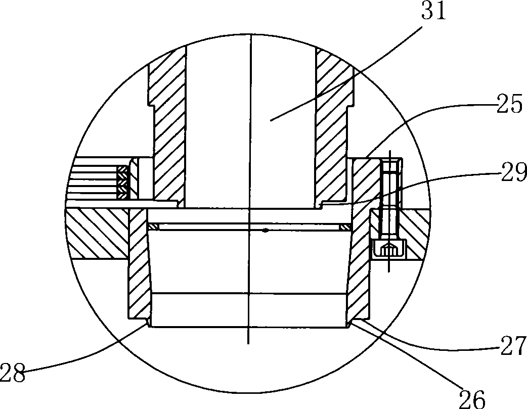
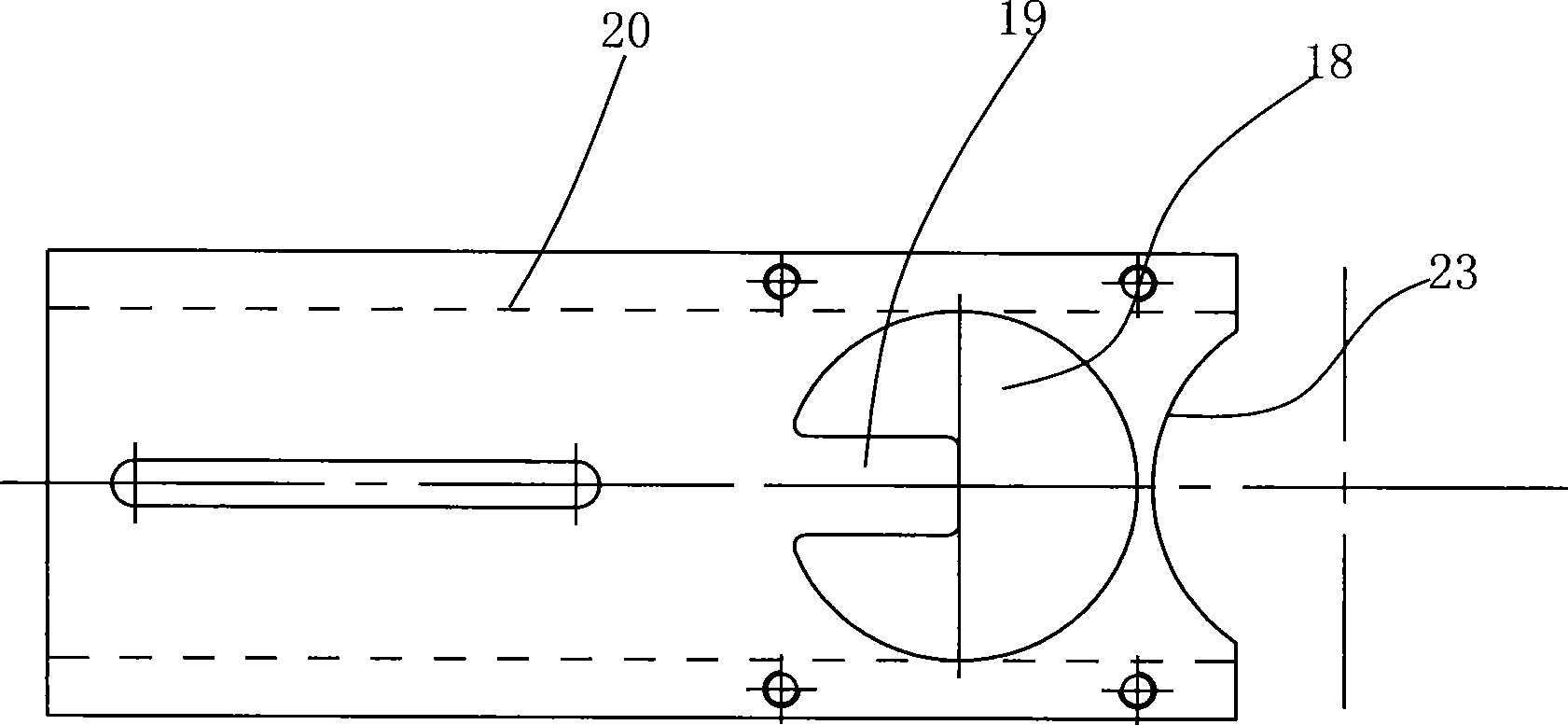
[0020] Embodiment 1: as figure 1 As shown, the bottom plate 1 is provided with two guide pillars 2 vertically arranged at intervals, the lower ends of the guide pillars 2 are fixed to the bottom plate 1, the upper ends of the guide pillars 2 are provided with a cylinder fixing plate 3, and the guide pillars between the bottom plate 1 and the cylinder fixing plate 3 The mandrel fixing plate 4 and the overcoat fixing plate 5 are connected by sliding up and down, the mandrel fixing plate 4 is located above the overcoat fixing plate 5 and is connected together by a compression spring 6 between the two, and the cylinder fixing plate 3 is fixed with a cylinder 7, The piston rod 8 of the cylinder 7 passes downward through the cylinder fixing plate 3 and is threadedly connected with the upper end of the clamping spring mandrel 9. The mandrel fixing plate 4 is provided with a mandrel installation through hole, and the upper end of the clamping spring mandrel 9 forms a diameter The prot...


PUM


Abstract

The invention relates to an internal circlip compacting device, which belongs to the technical field of circlip mounting device. A guide pole is arranged on a bottom board; a cylinder retaining plate is arranged at the upper end of the guide pole; the guide pole between the bottom board and the cylinder retaining plate is connected with a core rod retaining plate and an outer sleeve retaining plate in a sliding way; the core rod retaining plate and the outer sleeve retaining plate are connected by a compression spring; a piston rod of the cylinder is fixed with the upper end of a core rod of a compact circlip after the piston rod of the cylinder downward passes through the cylinder retaining plate; the core rod of the compact circlip and the core rod retaining plate are fixed together; an outer sleeve is arranged on the outer sleeve retaining plate; a hollow structure of the outer sleeve is coaxial with the core rod of the compact circlip, and has a taper hole section with larger upper end and small lower end; the lower end of the core rod of the compact circlip can pass through the position with the smallest inner diameter of the taper hole section of the hollow structure of the outer sleeve; and the bottom board is provided with a workpiece positioning plate corresponding to the lower side of the outer sleeve. The internal circlip compacting device has good guidance quality, can ensure that the circlip is smoothly assembled with convenient operation.

Description

technical field [0001] The invention relates to an inner clamp spring pressing device, which belongs to the technical field of clamp spring installation devices. technical background [0002] In the assembly structure of some motors, the axial positioning of parts such as the end cover is carried out by setting the inner circlip on the inner wall of the casing, that is, the groove for setting the inner circlip is formed on the inner wall of the casing, and then the The snap ring fits into the groove. During assembling, the jumper spring needs to be shrunk first and then put into the casing. After the jumper ring reaches the groove where the jumper ring is arranged, the jumper ring opens under its own elastic force and fits in the groove. [0003] Someone proposed a tooling for press-fitting the inner snap ring into the groove (notification number: CN2834799Y), which includes a machine base. There is a workpiece positioning base, and the inner snap ring is press-fitted into...

Claims


Application Information

Patent Timeline
Patent Type & Authority Applications(China)
IPC IPC(8): B25B27/20H02K15/00
CPCB25B27/20B23P19/084
Inventor 胡宏元吴晓峰
Owner ZHEJIANG LINIX MOTOR
Learn More