Printer-labeler and labeler

A technology for labeling machines and printers, applied to labeling machines, typewriters, labels, etc., can solve problems such as inability to ensure that labels are removed, and peeling has started

Inactive Publication Date: 2009-03-11
TOSHIBA TEC KK +1
View PDF1 Cites 32 Cited by
  • Summary
  • Abstract
  • Description
  • Claims
  • Application Information

AI Technical Summary

Problems solved by technology

[0005] However, in the case of employing the technique described in Patent Document 1 and in the case of using a label long in the conveying direction, there is a problem that when the RFID reader / writer detects a defect, the tip of the label has reached the peeling edge and the peeling has been completed. start
[0011] In the case of the second method, the removal of the label cannot be ensured, since the destination of the label blown off by the jet of air is not certain

Method used


Image

  • Printer-labeler and labeler
  • Printer-labeler and labeler
  • Printer-labeler and labeler

Examples


Embodiment Construction

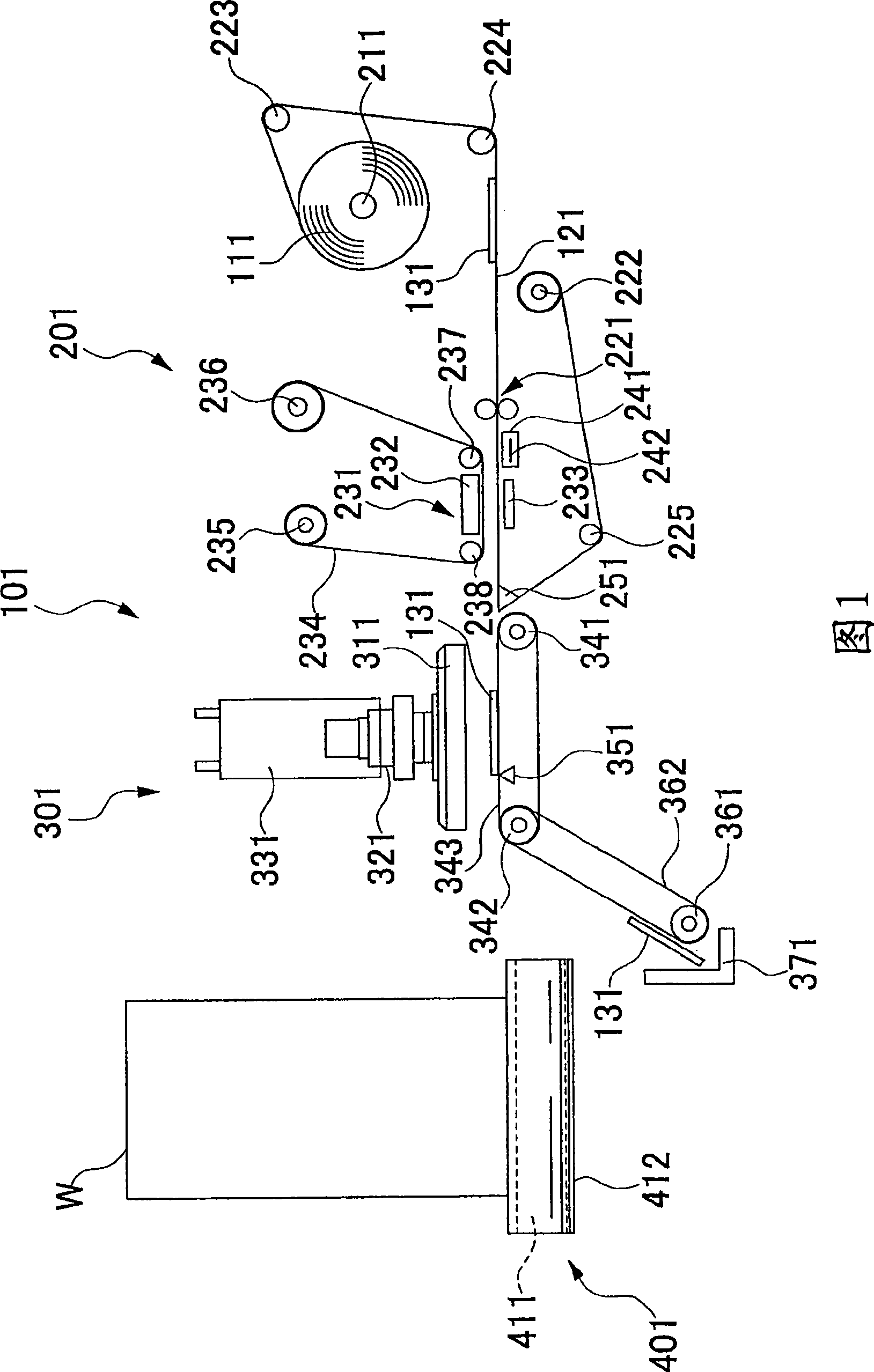
[0024] A printer-labelling machine and a labeling machine each embodying the present invention will be described below with reference to FIGS. 1 to 8 .

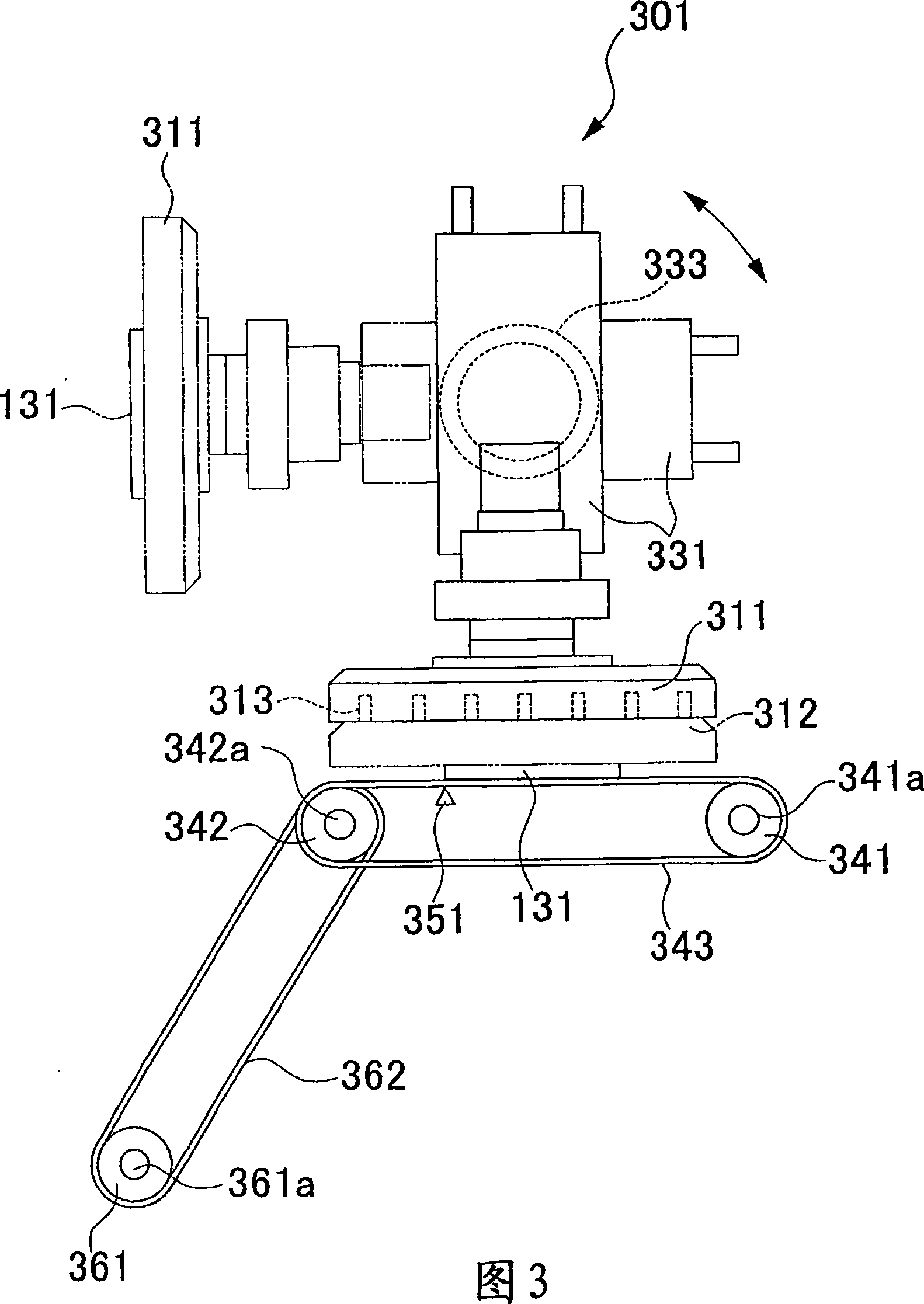
[0025] As shown in FIG. 1 , a printer-labeling machine 101 embodying the present invention mainly includes a printer 201 and a labeling machine 301 arranged side by side. Adjacent to the printer-labeller 101, a workpiece transfer unit 401 is provided. The workpiece transfer unit 401 transfers the workpiece W, which is an object to which the label 131 is to be attached, to a position facing the labeling machine 301 .

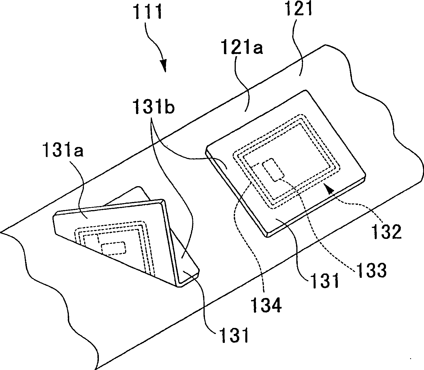
[0026] First, a description is given about the printer 201 . A holding shaft 211 that rotatably holds rolled label paper 111 is provided inside a housing (not shown) of the printer 201 . The label paper 111 has a structure in which a plurality of labels 131 are arranged at predetermined intervals on a long base paper 121 (see figure 2 ).

[0027] The label paper 111 held by the holding shaft 211 is drawn out...


PUM


Abstract

The invention provides a Printer-labeler and labeler. When a label (131) on a conveyor belt (343) is detected, there is performed a label sticking process of making a sticking mechanism (311, 331, 333) take out the label and stick it to an article (W) at a predetermined position, while when a defect of the label on the conveyor belt is detected before detecting the label, the label is sent out to a label recovery position without performing the label sticking process.

Description

technical field [0001] The invention relates to a printer-labelling machine and a labeling machine. Background technique [0002] Hitherto, a printer-labeller is known which comprises a printer and a labeler arranged side by side. In the printer section, write the RFID data of the RFID tag (tag) of the label, print to the label based on the print data, and peel the label from the base paper by rolling the label with the peeling edge (Japanese Laid-Open Publication No. 2005 -119687) (Patent Document 1). Although not clearly shown in Patent Document 1, there is known a printer-labeling machine in which, in the labeling machine section, chucking a label with a chucking head and then moving the label by the chucking head is performed. bit to paste the label. [0003] Occasionally there are cases where failures in tags result, for example, from defects in incorporated RFID tags. Such a failure of the tag can be detected, for example, by an infeasible communication of the RFID...

Claims


Application Information

Patent Timeline
Patent Type & Authority Applications(China)
IPC IPC(8): B65C9/00B65C9/18B65C9/40B65C9/26B41J3/407B41J2/32G06K17/00
CPCB65C9/40B65C2009/404B65C2009/0003B65C9/1884
Inventor 持田定义柏木伸市关本隆
Owner TOSHIBA TEC KK
Why Eureka
Try Eureka