
Vacuum pump unit

一种真空泵、主泵的技术,应用在泵元件、泵、电气元件等方向,能够解决降低润滑性能、泵寿命缩短、管误连接等问题,达到避免过载和腐蚀、有效泵抽运行、防止误连接的效果

Inactive Publication Date: 2009-02-25
EBARA CORP
View PDF0 Cites 2 Cited by
  • Summary
  • Abstract
  • Description
  • Claims
  • Application Information

AI Technical Summary

Problems solved by technology

The above water not only puts an excessive load on the pump, but also contaminates the lubricating oil of the bearing, which causes a reduced lubricating performance that greatly shortens the life of the pump
[0010] In addition, the arrangement of each group of pumps, conduits and valves that make up the vacuum pump unit is complicated
The complex arrangement described above will reduce the efficiency of the pumping operation and will also cause misconnection of the tubes and operational failure of the vacuum pump unit

Method used


Image

  • Vacuum pump unit
  • Vacuum pump unit
  • Vacuum pump unit

Examples


Embodiment Construction

[0052] Embodiments of the present invention will be described below with reference to the drawings. The same or corresponding elements are denoted by the same reference numerals and will not be repeatedly introduced.

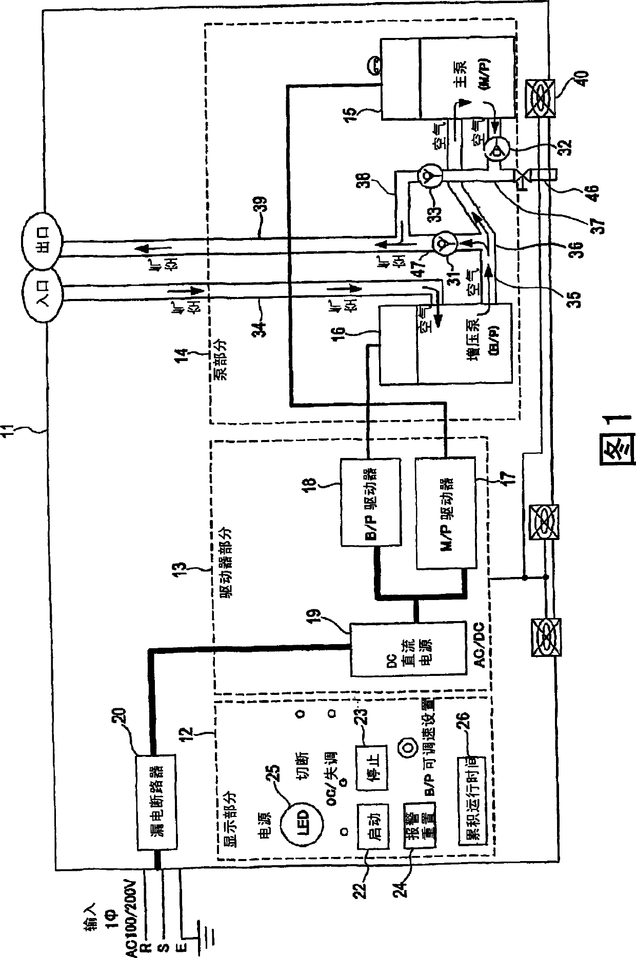
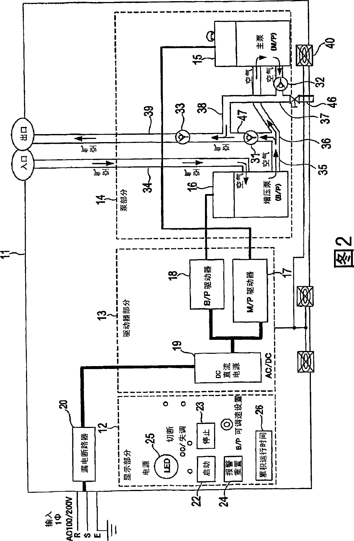
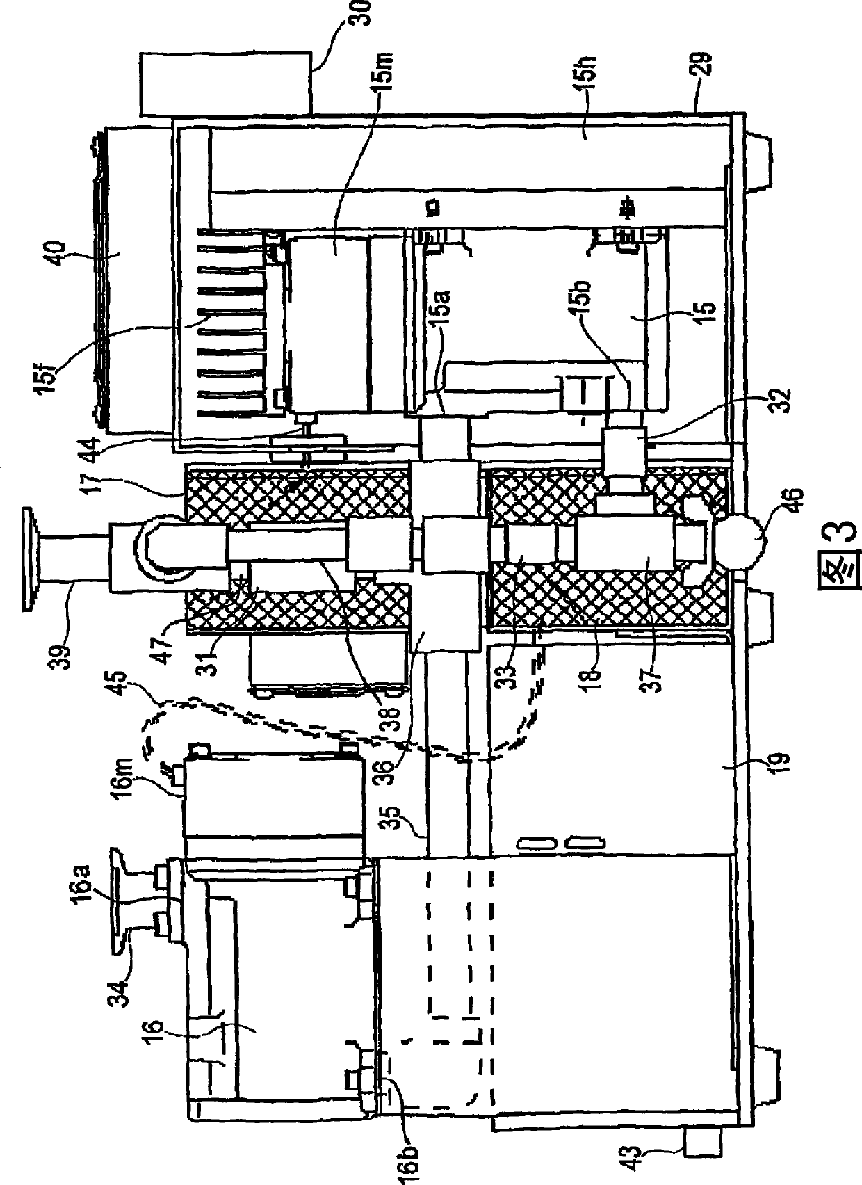
[0053] FIG. 1 is a schematic diagram showing a vacuum pump unit according to an embodiment of the present invention. FIG. 2 is a view showing a modified arrangement of valves shown in FIG. 1 . The vacuum pump unit 11 includes a display portion 12 , a driver portion 13 and a pump portion 14 . The pump section 14 includes two pumps, a main pump (rough vacuum pump) 15 and a booster pump 16 connected in series. These pumps have the same shape, same size and same displacement, ie, same structure. However, the main pump 15 and the booster pump 16 may have different structures.

[0054] Each of the vacuum pumps 15 and 16 is a two-shaft variable displacement screw pump that has no timing gears but uses a non-contact magnetic coupling that provides synchronous rotati...


PUM


Abstract

The present invention relates to a dry vacuum pump unit capable of achieving ultimate pressure of about 1 Pa. The vacuum pump unit includes a main pump (15) disposed at an outside-pressure side, and a booster pump (16) disposed at a vacuum side. The booster pump (16) and the main pump (15) are coupled in series. The booster pump (16) has a higher pumping speed than that of the main pump (15). Each of the main pump (15) and the booster pump (16) includes a pair of pump rotors (52a and 52b), a casing (50) having an inlet port and an outlet port, and a pair of magnet rotors (54 and 54) rotatable with the pair of pump rotors.

Description

technical field [0001] The present invention relates to a dry vacuum pump capable of achieving an ultimate pressure of about 1 Pa. Background technique [0002] Vacuum pumps having the above pumping performance are used in sputtering equipment, helium leak detectors, analyzers (eg, scanning electron microscope SEM), and the like. Further, the vacuum pump with the above-mentioned pumping performance is used as a rough vacuum pump connected with a high vacuum pump (such as a turbomolecular pump, etc.), and can also be used in a vacuum desiccator or a vacuum bonded (vacuum bonded) absorbing gas (such as water vapor, etc.). bonding) equipment. [0003] Oil-sealed rotary pumps are generally used as small-sized, portable and inexpensive small-capacity vacuum pumps. However, this type of pump presents problems including backdiffusion of oil vapor into the vacuum chamber (contamination of the vacuum chamber and workpiece), oil contamination of the discharge piping (fire), environm...

Claims


Application Information

Patent Timeline
Patent Type & Authority Applications(China)
IPC IPC(8): F04C23/00F04C18/16F04C25/02F04C28/02H02K49/10
CPCH02K7/11F04C28/24F04C25/02F04C23/00F04C23/001F04C18/16H02K16/00F04C29/0085F04C28/02
Inventor 穗积崇史宫下信人稻田高典真武幸三小岛善德三宅晋臼井克明
Owner EBARA CORP
Learn More