Tri-state overrunning clutch

A technology of overrunning clutches and outer rings, applied in clutches, one-way clutches, mechanical equipment, etc., can solve problems such as wear, affecting service life, and single function

Active Publication Date: 2009-02-25
BYD CO LTD
View PDF3 Cites 22 Cited by
  • Summary
  • Abstract
  • Description
  • Claims
  • Application Information

AI Technical Summary

Problems solved by technology

[0004] However, in the existing overrunning clutches, the overrunning state and engaged state of the overrunning clutch are realized through the relative rotation between the inner and outer rings, and the clutch itself has no additional mechanism to control the working position of the sprags, so there are The problem is that the overrunning clutch only has a one-way overrunning state and a one-way engaging state, and has a single function
In some specific construction machinery applications, when the overrunning clutch is required to rotate at high speed, the driving part and the driven part are completely separated, that is, the driving part and the driven part can not interfere with each other, and the one-way overrunning of the overrunning clutch limits the this function
At the same time, when the clutch is in the high-speed overrunning state, the wedge is in contact with the inner and outer rings, so there are problems of wear and heat, which will affect its service life

Method used


Image

  • Tri-state overrunning clutch
  • Tri-state overrunning clutch
  • Tri-state overrunning clutch

Examples


Embodiment Construction

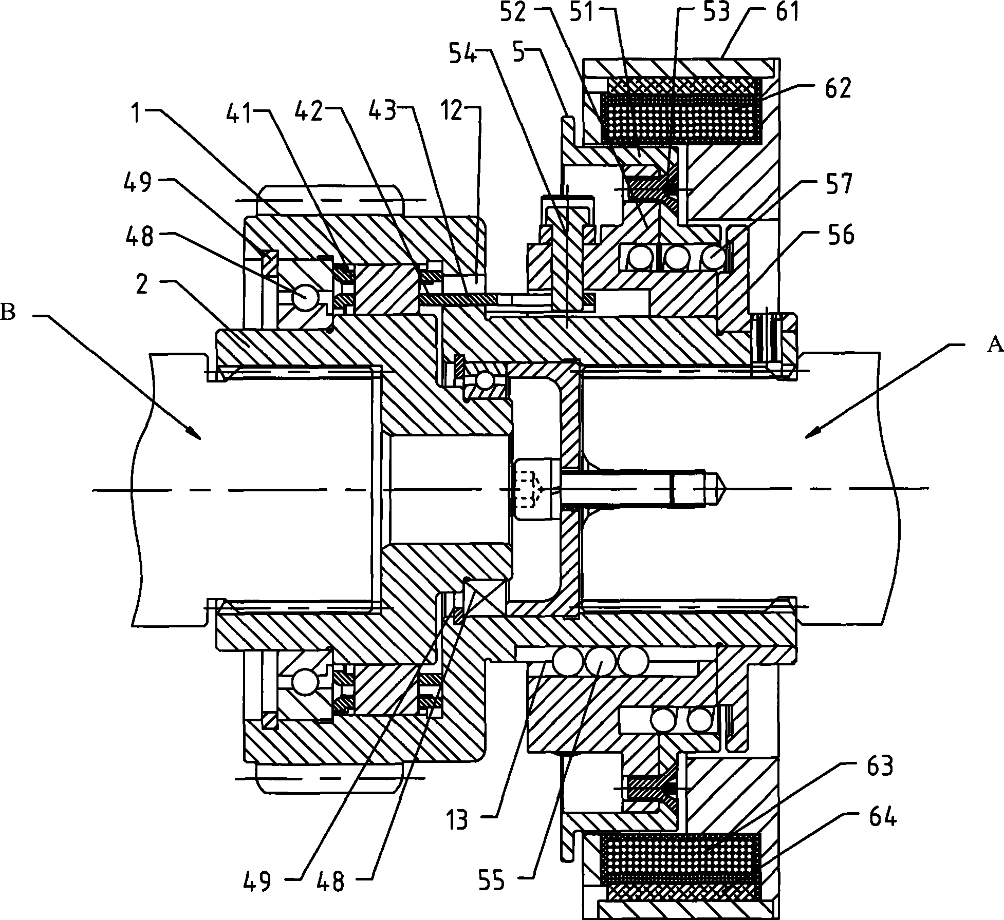
[0028] Specific embodiments of the present invention will be described in detail below with reference to the accompanying drawings.

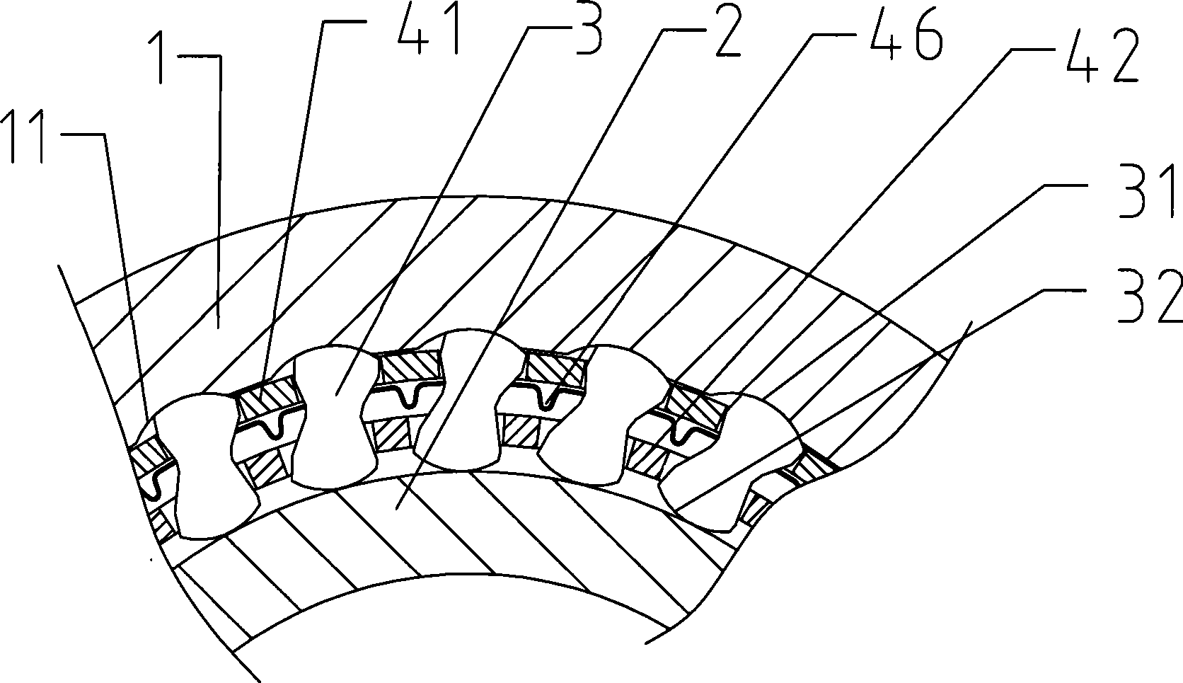
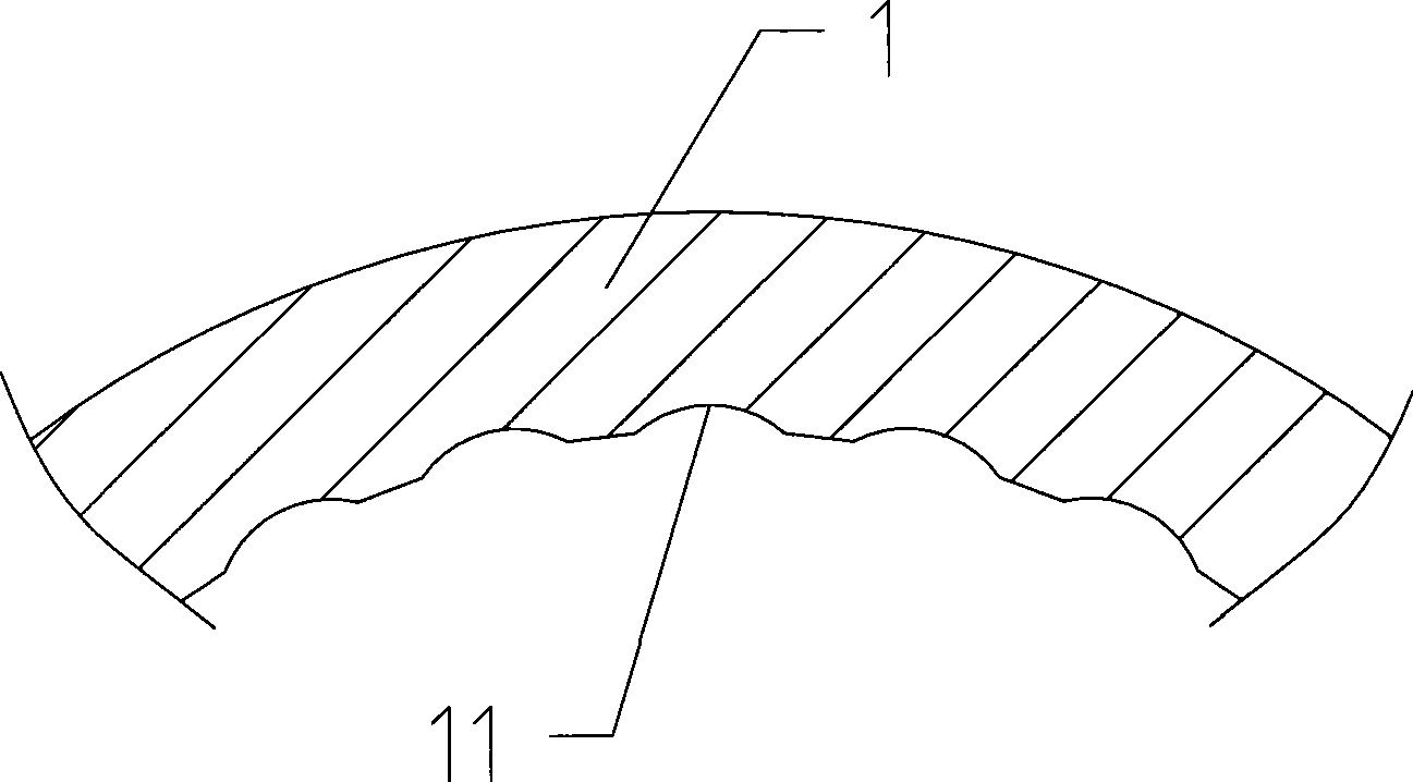
[0029] As shown in the figure, a three-state overrunning clutch provided by the present invention includes an outer ring 1, an inner ring 2, a plurality of sprags 3 located between the outer ring 1 and the inner ring 2, and a plurality of sprags 3 located between the outer ring 1 and the inner ring 2. The outer holder 41 and the inner holder 42 of the plurality of wedges 3 are held between them and for example through holding holes. There are a plurality of arc grooves 11 on the working surface of the outer ring 1, and each arc groove 11 cooperates with a working surface 31 of a corresponding wedge 3, and keeps the working surface 31 on the circle. In the arc groove 11. The inner cage 42 has a plurality of protrusions 43 protruding axially outward, and each protrusion 43 has an oblique hole 44 inclined relative to the axial direction. An axial...


PUM


Abstract

The invention provides a three-state overrunning clutch which comprises an outer circle, an inner circle, a plurality of wedge blocks positioned between the outer circle and the inner circle, and an outer holding rack and an inner holding rack positioned between the outer circle and the inner circle and holding the plurality of wedge blocks. A plurality of arc grooves are formed on the working face of the outer circle and each arc groove is matched with a working face of the corresponding wedge block and holds the working face inside the arc groove; the inner holding rack is provided with a plurality of protruding plates axially extending outwards, and each protruding plate is provided with oblique holes inclined relative to the axial direction. An axial sliding poke tray is arranged on the outer circumference of the outer circle, wherein a plurality of poke rods, which are respectively inserted into the corresponding oblique holes, are fixed on the poke tray. Through the electromagnetic driving mechanism, the poke tray slides axially on the outer circumference of the outer circle. By removing the poke tray, the wedge blocks are controlled to completely move off the working face of the inner circle, so that the outer circle and the inner circle can rotate freely in both the positive and the negative directions, thus achieving the two-way separating working state of the three-state overrunning clutch.

Description

technical field [0001] The invention relates to an overrunning clutch, in particular to a three-state overrunning clutch, which can control the inner ring and the outer ring of the overrunning clutch to be completely disengaged from each other so as to freely rotate in forward and reverse directions. Background technique [0002] An overrunning clutch, also known as a one-way clutch or a one-way bearing, is a device that can only transmit torque in one direction of rotation. Existing overrunning clutches mainly include roller type overrunning clutches and sprag type overrunning clutches. [0003] As an example of a sprag type overrunning clutch, CN 2476675Y (or CN 1430000A) discloses a kind of overrunning clutch with double cages, the overrunning clutch includes an inner ring and an outer ring, and a plurality of Wedges, and these wedges are held by the holding holes opened in the double cage (including the inner cage and the outer cage) between the inner and outer rings. ...

Claims


Application Information

Patent Timeline
Patent Type & Authority Applications(China)
IPC IPC(8): F16D41/08
Inventor 任毅杨胜麟郭松岳谭国栋
Owner BYD CO LTD
Why Eureka
Try Eureka