
Heat insulation lens set

A lens group and lens technology, applied in the direction of electronic circuit testing, measuring devices, instruments, etc., can solve problems such as damage to the machine, short circuit, light confusion, etc.

Inactive Publication Date: 2009-02-11
KING YUAN ELECTRONICS
View PDF0 Cites 0 Cited by
  • Summary
  • Abstract
  • Description
  • Claims
  • Application Information

AI Technical Summary

Problems solved by technology

When the relatively low temperature surface is very close to the relatively high temperature surface, a layer of water vapor will be generated at the overall interface, which can also be called saturated water; therefore, when the light source continues to illuminate, the light will pass through the water molecules and make the light Physical phenomena such as reflection, scattering or diffraction will not only confuse the light reaching the chip to be tested, which will cause errors in the test results, but also cause unnecessary short circuits and damage the machine.

Method used


Image

  • Heat insulation lens set
  • Heat insulation lens set
  • Heat insulation lens set

Examples


Embodiment Construction

[0022] The direction of the present invention discussed here is a testing machine. In order to provide a thorough understanding of the present invention, detailed steps and components thereof will be set forth in the following description. Clearly, the practice of the invention is not limited to specific details familiar to those skilled in the testing machine. On the other hand, the components or steps of well-known testing machines are not described in detail in order to avoid unnecessary limitations of the present invention. The preferred embodiments of the present invention will be described in detail as follows, however, the present invention can be widely implemented in other embodiments besides these detailed descriptions, and the scope of the present invention is not limited, which is subject to the claims.

[0023] In the prior art, the chip to be tested (hereinafter referred to as the chip to be tested) of the photosensitive element will be kept in a low temperature...


PUM


Abstract

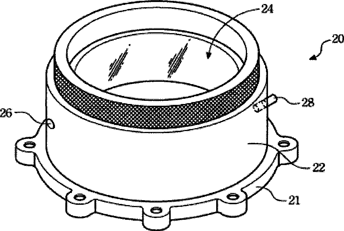
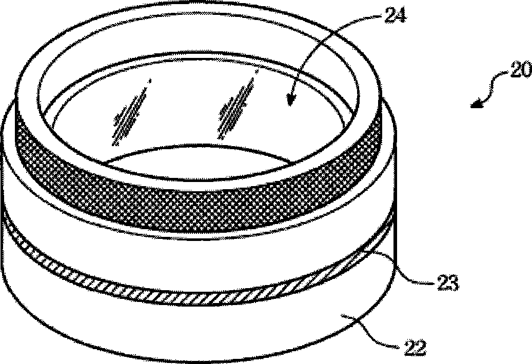
The invention discloses a heat insulating lens group, which is arranged in a hollow opening of a spring needle head sea. The heat insulating lens group comprises a lens main body and two lenses arranged in parallel. A sealed space separated by the lens main body and two lenses arranged in parallel is kept under vacuum.

Description

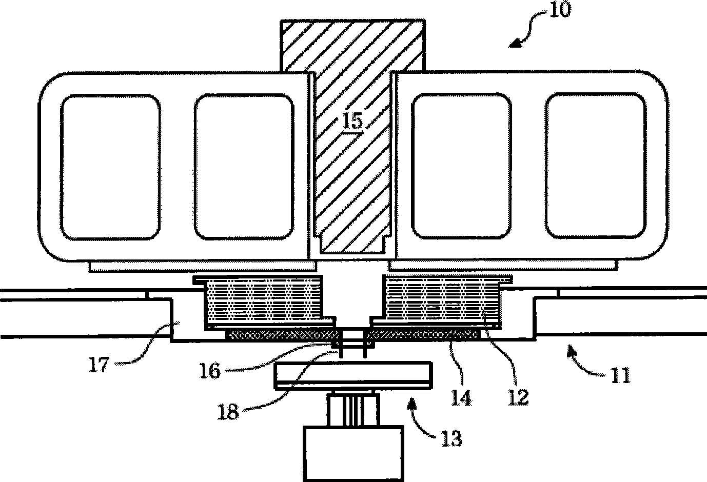
technical field [0001] The invention relates to a test machine for testing a photosensitive element, in particular to a test machine which isolates the surface of a chip to be tested from the surface irradiated by a light source with a closed space formed by a heat-insulating lens group. Background technique [0002] In order to make the photosensitive element (such as: CMOS Sensor) maintain normal function in the low temperature environment, therefore, the chip of the photosensitive element needs to be tested in the low temperature environment during the testing stage. [0003] figure 1 It is a schematic diagram of a test machine 10, the upper part is a test seat 11, and the lower part is a pad device (chuck) 13 for placing the chip to be tested. The test socket 11 includes a pogo tower (POGO Tower) 12, a test probe card (Probe Card) 14 and a test head (Test Head) 16, and the test head 16 is provided with a test probe 18 that contacts the chip to be tested. A cavity 15 th...

Claims


Application Information

Patent Timeline
IPC IPC(8): G01R31/28G01R31/00G01R1/02G01R1/073
Inventor 戴碧辉
Owner KING YUAN ELECTRONICS
Learn More