
Adapter gear box in pre-control

A gearbox and pre-control technology, which is applied to vehicle gearboxes, bicycle gear shifting mechanisms, bicycle accessories, etc., can solve the problems of heavy gearbox weight, unsmooth shifting operation, and inability to meet various needs of operation modes, etc. Compact structure and weight saving effect

Active Publication Date: 2009-02-11
郭渠汉
View PDF1 Cites 1 Cited by
  • Summary
  • Abstract
  • Description
  • Claims
  • Application Information

AI Technical Summary

Problems solved by technology

[0003] 1. Due to the installation of the spinning ring through the collar in the shield and the connection of the support seat between the standpipe and the leather case, the weight of the gearbox is heavy;
[0004] 2. The spinning ring of the second-speed controller is "V"-shaped, which makes the speed change operation not smooth;
[0005] 3. There is only a controller with a handlebar, which cannot meet the various needs of the operation mode

Method used


Image

  • Adapter gear box in pre-control
  • Adapter gear box in pre-control
  • Adapter gear box in pre-control

Examples


Embodiment 1

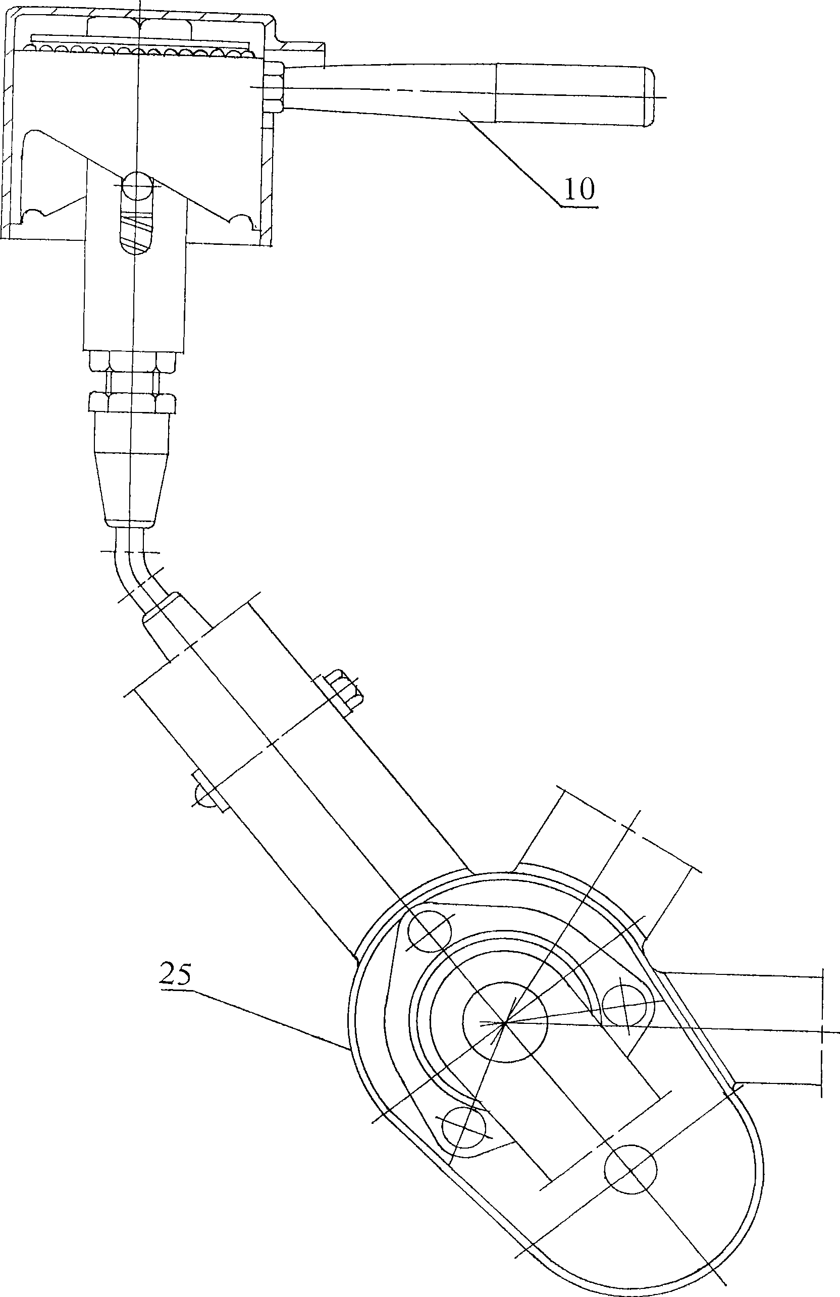
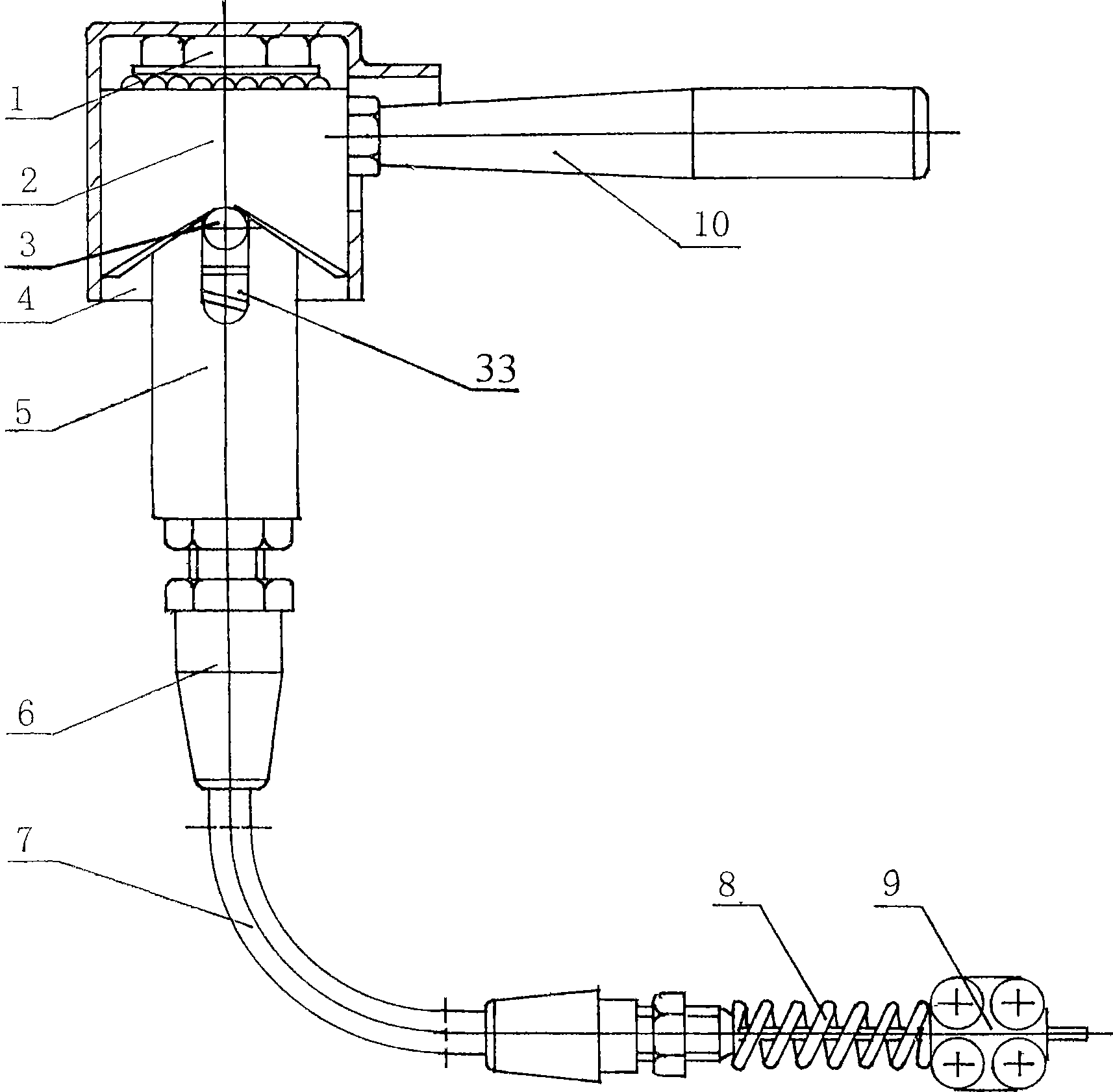
[0022] see image 3 , Figure 4 , Figure 7 , present embodiment comprises controller and gearbox, and controller is installed on the handlebar of bicycle or tricycle, or the position that other wants to install, and it comprises operating rod 10, protective cover 4, standpipe 5 and wire clip 9, in protective A spinning ring 2 is installed in the cover 4 through a nut 1 , and an operating rod 10 is connected to the spinning ring 2 . There is a U-shaped groove 33 at one end of the standpipe 5, and there is a slider 12 at one end of the U-shaped groove in the standpipe. . The other end of standpipe 5 connects guide tube 7 by leather sheath 6, connects small spring 8 at the other end of guide tube 7, and the other end of little spring 8 connects wire clip 9, and one end of slide block in standpipe 5 connects steel wire 34 and Surrounding the large spring 13 outside the steel wire, the steel wire 34 passes through the conduit 7 and the small spring 8 to be connected to the lin...

Embodiment 2

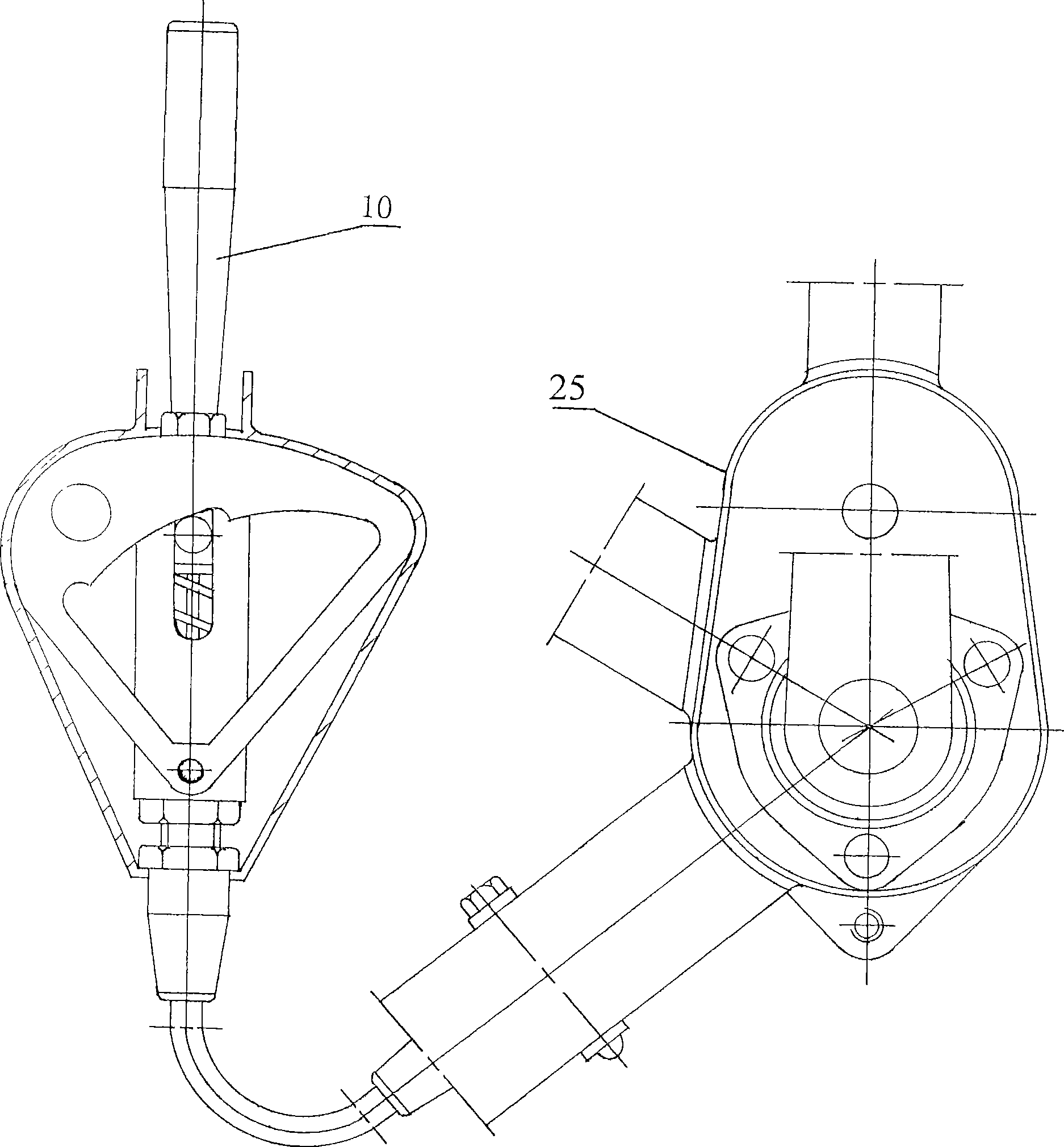
[0024] see Figure 5 , Figure 6 , Figure 7 , the controller of this embodiment is a Shunba two-speed controller, and the other structures are the same as those of Embodiment 1. The operating rod 10 of the controller is connected to the top of the spinning ring 2 , the lower end of the spinning ring 2 is connected to the lower end of the standpipe 5 through a pin 15 , and the protective cover 4 is covered on the lower end of the standpipe 5 .

Embodiment 3

[0026] see figure 1 and Figure 8 , the gearbox of this embodiment is a three-speed gearbox. Compared with Embodiment 1, a three-tooth reverse gear 23 is installed on the rear axle 24 through a rear needle bearing 31, and there is one more middle gear than the two-speed reverse gear. Teeth 32, constitute a three-speed gearbox with left, middle and right gears (see Figure 8 ). The controller is a three-speed handlebar controller, and the spinning ring of the three-speed controller is one more step than that of the two-speed controller (see figure 1 ). Other structures are the same as in Embodiment 1.


PUM


Abstract

The invention discloses a pre-control middle connector variable speed case, which relates to a variable speed box, in particular to a gear variable speed box used for a bicycle or a tricycle. The variable speed box comprises a controller and a variable speed case, the controller comprises an operating lever, a protective cover, a vertical tube and a wire clip, and a steel wire in the vertical tube is connected with the wire clip. The variable speed case comprises a case body and a gear in the case body, a cover box is connected with the case body, the wire clip is positioned in the cover box, a shifting fork is installed in the cover box, and the other end of the shifting fork is positioned in the case box. A front axle and a rear axle are installed in the case box, a bull gear and an output gear are respectively connected with both ends of the front axle, a clutch is installed between the bull gear and the output gear, the shifting fork is connected to the clutch, and a reverse gear is installed on the rear axle through a rear roller pin bearing. The variable speed box adopts the key technology that a rotary extrusion ring is installed through a bearing; a supporting tube is connected between the vertical tube and a leather sheath, and the steel wire penetrates into the supporting tube and gets into a conduit tube. The variable speed box has the advantages of good performance, small volume and light weight, and is more suitable for the gear change of the bicycle or the tricycle to be popularized.

Description

(1) Technical field: [0001] The invention relates to a speed change device, in particular to a gear speed change device for bicycles and tricycles. (two) background technology: [0002] At present, the world produces 250 million bicycles every year, of which China accounts for 1 / 3, not including three-wheeled bicycles. Popularizing bicycle speed change is the development direction of Chinese bicycles. However, bicycle speed change is an unsolved technical problem in the global bicycle industry, so the utilization value of bicycles has not been improved. If bicycle speed change is popularized, the value of bicycles will increase by 1 / 3. The inventor obtained the patent No. 96117624.5 on May 22, 2002 for the invention patent of "Bicycle Middle Joint Gearbox". This patented product has made an important contribution to the popularization of bicycle gear shifting, but this patented product also has the following problems that affect The popularity of bicycle gear shifting: ...

Claims


Application Information

Patent Timeline
IPC IPC(8): B62M11/04B62M25/04
Inventor 郭渠汉郭智强
Owner 郭渠汉
Learn More