Solder reflow sample position limiter

A limiting device, reflow soldering technology, applied in auxiliary devices, welding equipment, auxiliary welding equipment, etc., can solve the problems of wasting a lot of manpower and material resources, sample size changes, poor versatility, etc., to achieve easy adjustment, eliminate limit Inaccurate or unstable, simple-structured effects

Inactive Publication Date: 2009-02-11
TIANJIN UNIV
View PDF0 Cites 4 Cited by
  • Summary
  • Abstract
  • Description
  • Claims
  • Application Information

AI Technical Summary

Problems solved by technology

Due to the variety of joint types in the test (such as Figure 12(a) , 12(b) , 12(c), 12(d), and 12(e)), the sample size varies greatly, and it will waste a lot of manpower and material resources to make corresponding limit devices for each joint type and each size test piece , so there is an urgent need for a device that can meet the limit requirements of various common joint samples and common components
At present, most researchers paste the sample on the flat plate to limit the position in the test. The main disadvantage of this method is that the sample is seriously shifted due to the melting of the adhesive during the welding process. Some researchers also fix the column The main disadvantage of this method is that the sample is limited on the flat plate. The size of the sample changes slightly, and the device needs to be greatly changed.

Method used


Image

  • Solder reflow sample position limiter
  • Solder reflow sample position limiter
  • Solder reflow sample position limiter

Examples


Embodiment Construction

[0031] The reflow soldering sample limiting device of the present invention will be described in detail below in combination with the embodiments and the accompanying drawings.

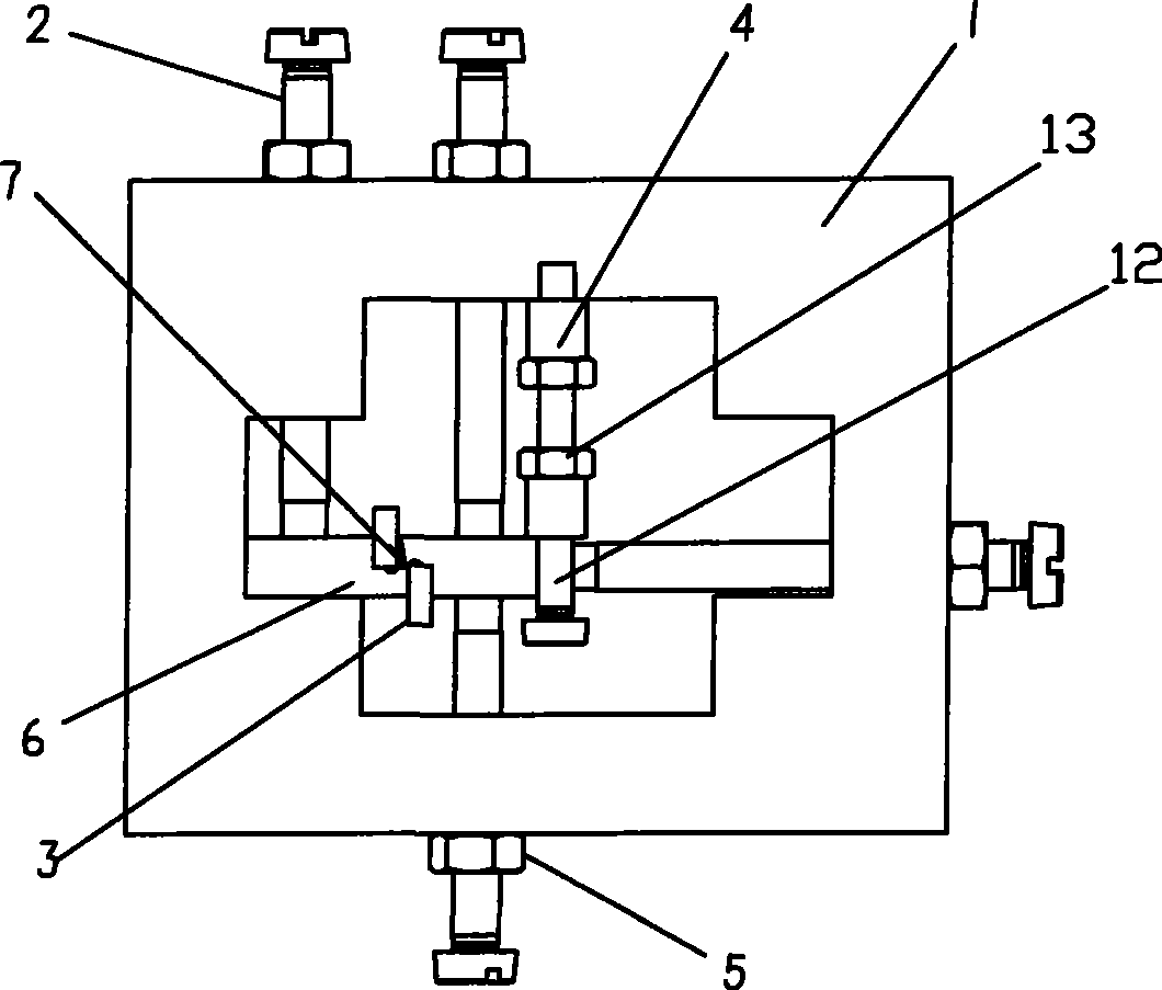
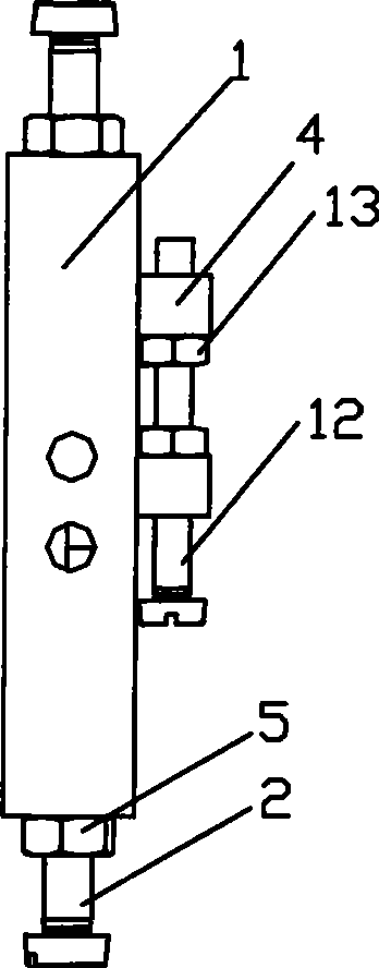
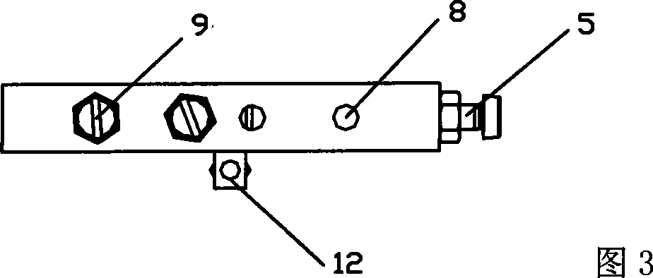
[0032] Such as figure 1 , Figure 3~ Figure 7 As shown, the reflow soldering sample limiting device of the present invention includes a frame 1 for placing the sample 6 to be soldered, a plurality of feed bolts 2 and lock nuts 5 for limiting the sample 6, and a plug Block 3: the frame 1 is a rectangular frame structure, and the sample 6 to be positioned is arranged in the space of the cross-shaped opening inside the frame 1, and corresponding through holes are formed on each two symmetrical frames constituting the frame 1 along the plane direction. Threaded holes 8, wherein two or more through threaded holes 8 are respectively formed on the two long frames of the rectangular frame 1, and one through threaded holes 8 are respectively formed on the two short frames of the rectangular frame 1 or more ...


PUM


Abstract

A reflow soldering sample-limiting device consists of a frame used for setting welded samples, a feed bolt and a locking nut which are used for positioning the samples and a chock. The structure of the frame is a rectangular frame, the inner space of the frame is provided with the limited sample and every two symmetric edge frames forming the frame respectively form corresponding screw holes along the plane direction; the through screw holes used for running through the edge frame by the feed bolt support the samples and is locked by locking the nut, and the chock is plugged into the gaps of the samples. The device also comprises an adjusting slider the end of which forms the through screw hole, an adjusting bolt which runs through the through screw hole on the adjusting slider, and an adjusting nut used for adjusting the adjusting bolt and the adjusting slider; the adjusting bolt is positioned on the upper part of the frame; and the adjusting slider which is sheathed on the adjusting bolt is positioned between the sample and a frame which is parallel with the sample through an adjusting card of the adjusting nut. The invention has the advantages of high limited precision, simple structure and easy adjustment with the precision of up to 0.02mm and can effectively eliminate the defects such as serious sample offset and the like during the process of welding.

Description

technical field [0001] The invention relates to a position limiting device. In particular, it relates to a testing reflow soldering sample limiting device with high positioning accuracy, simple structure, convenient adjustment and the ability to meet the limiting requirements of various commonly used joint samples and component reflow soldering. Background technique [0002] The reflow soldering process is widely used in electronic packaging. The precise positioning of components or samples during the soldering process is very important to ensure the soldering quality. In large-scale production, components are usually fixed and positioned by vacuum adsorption or fixed on a positioning pallet to limit the components, while in new product development tests, it is more often necessary to limit various joint samples. Due to the variety of joint types in the test (such as Figure 12(a) , 12(b) , 12(c), 12(d), and 12(e)), the sample size varies greatly, and it will waste a lot o...

Claims


Application Information

Patent Timeline
Patent Type & Authority Applications(China)
IPC IPC(8): B23K3/08B23K37/04H01L21/60
Inventor 荆洪阳张国尚徐连勇
Owner TIANJIN UNIV
Why Eureka
Try Eureka