
Pulsating direct current traction electric power supply system

A traction power supply system, pulsating DC technology, applied in power lines, irreversible AC power input conversion to DC power output, transportation and packaging, etc. It can improve the reliability of power supply, solve the load imbalance, and improve the terminal voltage level.

Inactive Publication Date: 2010-06-09
BEIJING JIAOTONG UNIV
View PDF4 Cites 0 Cited by
  • Summary
  • Abstract
  • Description
  • Claims
  • Application Information

AI Technical Summary

Problems solved by technology

The existing problems are: 1. Since the power frequency single-phase AC 25KV traction network is an asymmetrical power supply circuit for the power device, the load of the power device is unbalanced and the negative sequence component is relatively large.
3. The low voltage level at the end of the catenary is also one of the important reasons for restricting the high-speed running of trains

Method used


Image

  • Pulsating direct current traction electric power supply system
  • Pulsating direct current traction electric power supply system
  • Pulsating direct current traction electric power supply system

Examples


Embodiment 1

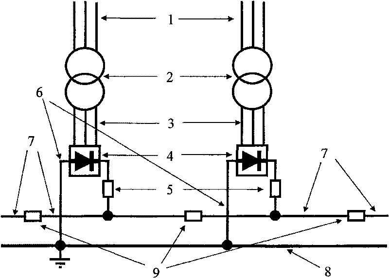
[0016] Such as figure 1 As shown, the pulsating DC traction power supply system consists of three-phase 220KV or 110KV power supply input terminal (1), three-phase 220KV / 25KV or 110KV / 25KV traction transformer (2), traction power supply three-phase output 25KV busbar (3) , three-phase rectification device (4), 25KV pulsating DC output circuit breaker (5), return line (6), electrified railway power supply section catenary (7), rail (8) and catenary contact circuit breaker (9) composition.

[0017] The input terminal of the three-phase 220KV or 110KV power supply of the power device is (1) connected to the three-phase 220KV / 25KV or 110KV / 25KV traction transformer (2), the three-phase output 25KV busbar for traction power supply (3), and the three-phase rectifier (4 ), a 25KV pulsating DC output circuit breaker (5), and a return line (6) form a traction power supply transformation system. A plurality of electrified railway power supply section catenaries (7) are connected into ...

Embodiment 2

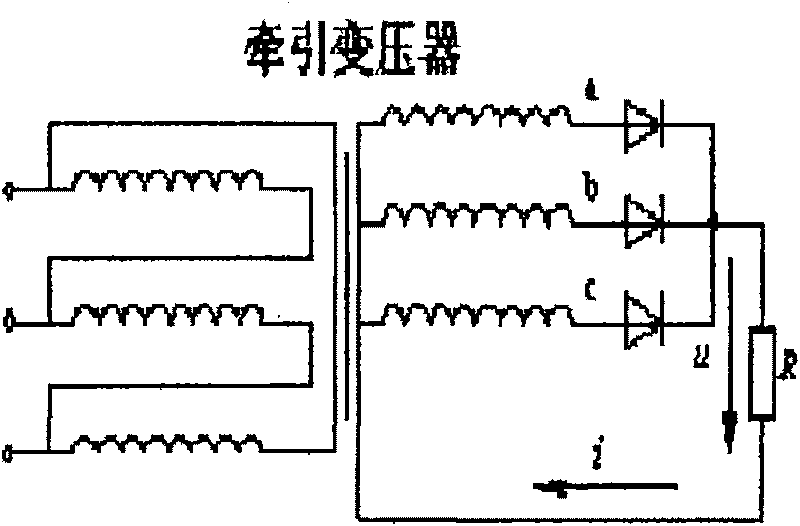
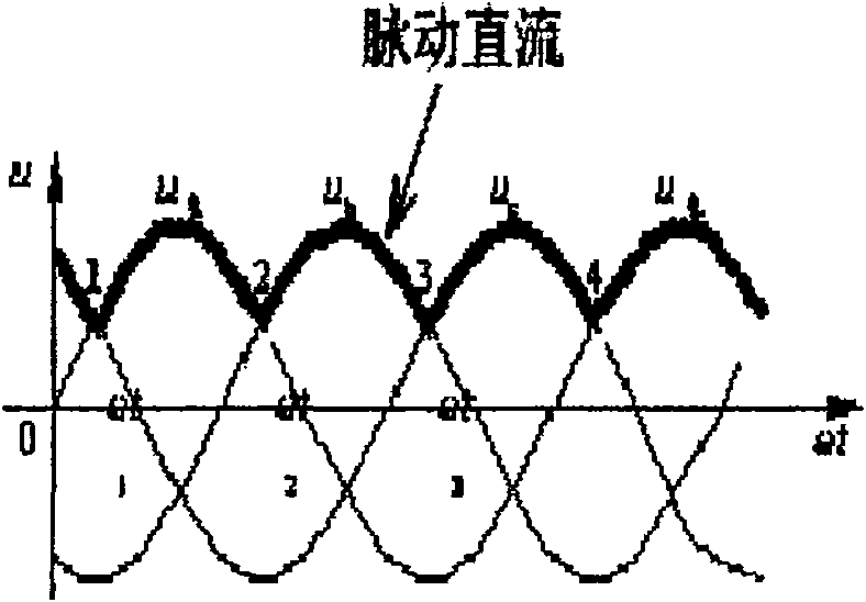
[0020] The schematic wiring diagram and output voltage waveform diagram of the three-phase rectifier (4) are shown in Figure 2-Figure 5 .

[0021] figure 2 , image 3 It is the schematic wiring diagram and the output voltage waveform diagram of the three-phase half-wave rectifier (4). It can be seen from the figure that the voltage on the load R of the electric locomotive is a pulsating DC voltage.

[0022] Figure 4 , Figure 5 It is the schematic wiring diagram and the output voltage waveform diagram of the three-phase full-wave rectifier (4). It can be seen from the figure that the voltage on the load R of the electric locomotive is a pulsating DC voltage.


PUM


Abstract

The invention discloses a pulsating direct current traction power supply system. The three-phrase 220KV or 110KV power supply input end of a power device is connected with a three-phrase 220KV / 25KV or110KV / 25KV traction transformer; the three-phrase 220KV / 25KV or 110KV / 25KV traction transformer is connected with a traction power supply three-phrase output 25KV bus; the traction power supply three-phrase output 25KV bus is connected with a three-phrase rectifying device; one end of the three-phrase rectifying device is connected with a 25KV pulsating direct current output breaker; the other end of the three-phrase rectifying device is connected with a return cable; the other end of the 25KV pulsating direct current output breaker is connected with a power supply section contact network; the return cable is connected with a rail; a traction power supply substation is formed; a plurality of power supply section contact networks of an electrified railway are connected into a contact network by a contact network interconnection breaker; each traction power supply substation is connected with one power supply section contact network. The system has the advantages of solving the problemof unbalanced load of the power device, avoiding the problem of phrase passing of different phrases, greatly improving the terminal voltage level of the contact network as well as the power supply reliability owing to the parallel power supply of the traction substation.

Description

technical field [0001] The invention relates to an electrified railway traction power supply system, which is a pulsating DC traction power supply system and belongs to the field of railway energy. Background technique [0002] my country's electrified railway adopts 25KV power frequency single-phase AC system, and the power source comes from the electric device near the railway line. The voltage of the power device is generally 220KV or 110KV, which is a three-phase symmetrical device. The function of the traction substation is to transform the three-phase 110KV (or 220KV) high-voltage alternating current into two single-phase 27.5KV alternating currents, and then supply power to the catenary (rated voltage 25KV) in the up and down directions of the railway. The existing problems are: 1. Since the power frequency single-phase AC 25KV traction network is an asymmetrical power supply circuit for the electric device, the load of the electric device is unbalanced and the negat...

Claims


Application Information

Patent Timeline
Patent Type & Authority Patents(China)
IPC IPC(8): B60M3/00B60M3/04H02M7/06
Inventor 刘平竹
Owner BEIJING JIAOTONG UNIV
Learn More