Novel inclined pin ejecting structure

A new type of oblique tip technology, applied in the field of oblique tip ejection structure, can solve problems such as inapplicability, and achieve the effects of simple structure, good promotion value, and reduced extension length.

Inactive Publication Date: 2009-01-21
MITAC PRECISION TECH(KUNSHAN) CORP
View PDF0 Cites 5 Cited by
  • Summary
  • Abstract
  • Description
  • Claims
  • Application Information

AI Technical Summary

Problems solved by technology

[0005] In view of the above problems, the present invention provides a new type of inclined-tip ejection structure to overcome the defect that the existing inclined-tip ejection structure is not suitable for products with two or more barbs with relatively close distances on the ejection surface

Method used


Image

  • Novel inclined pin ejecting structure
  • Novel inclined pin ejecting structure
  • Novel inclined pin ejecting structure

Examples


Embodiment Construction

[0012] In order to have a further understanding of the structure, composition and technical characteristics of the present invention, the following will be described in detail in conjunction with the accompanying drawings:

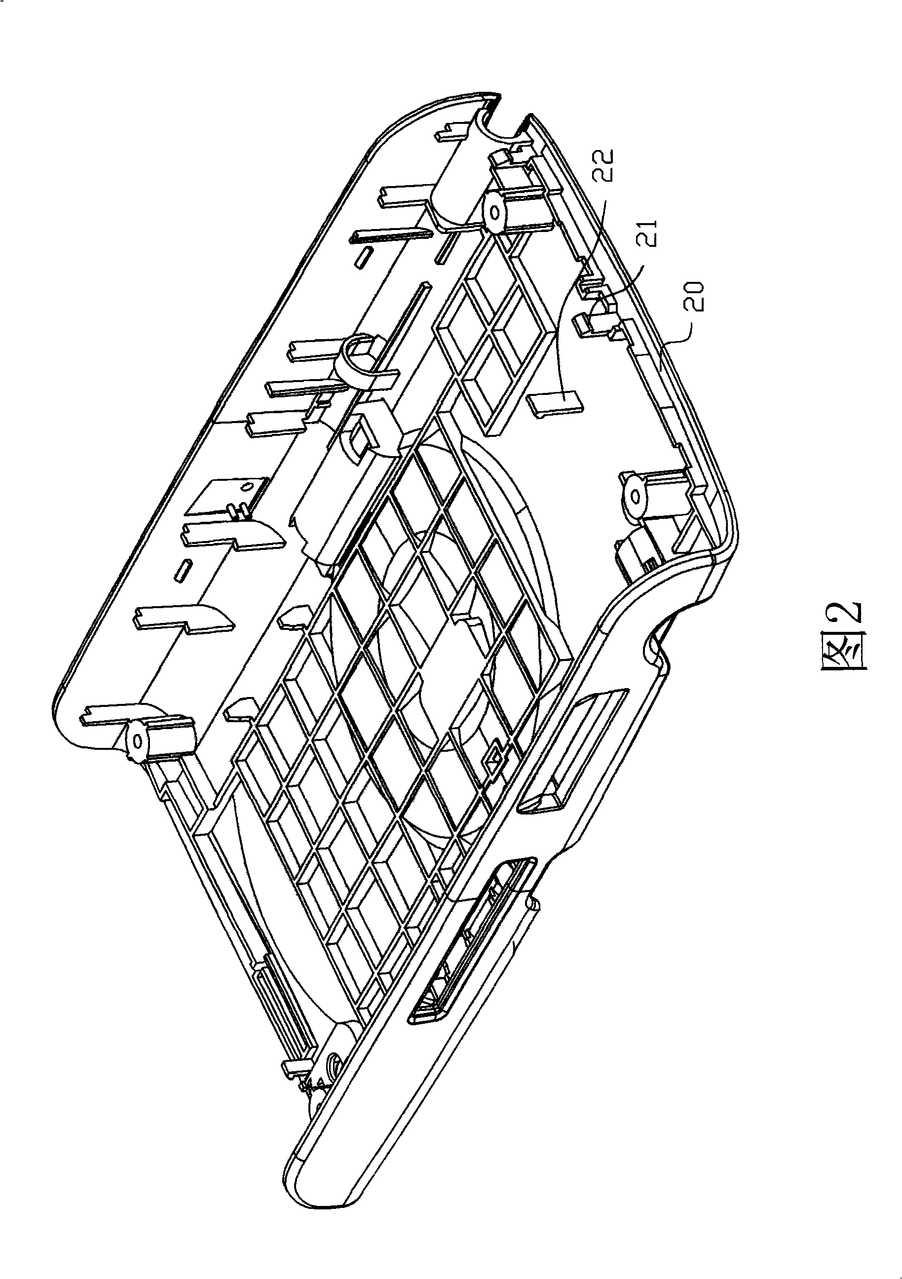
[0013] The present invention is designed for products that cannot be ejected from the surface with two or more barbs that are relatively close to each other in the prior art. As shown in Figure 2, the surface opposite to the male die core (not shown) There are two barbs 21 and 22 on the side, and the distance between the barb 21 and the barb 22 is relatively close.

[0014] Please refer to Figure 2 and image 3 shown, where image 3 It is a schematic diagram of the ejection structure of the new oblique tip; the ejection structure of the oblique tip is suitable for a mold structure, the mold includes a male template 30, the male template 30 is provided with a male mold core 31, and an ejector is provided below the male template 30. plate 33, the mold also...


PUM


Abstract

The invention relates to a novel inclined pin knockout structure which is suitable for a mould structure. The mould comprises a core plate which is provided with a core, a knockout plate is arranged below the core plate, wherein, the inclined pin knockout structure comprises a inclined pin boss, at least two inclined pins and a knockout part; the inclined pin boss is arranged in the core plate; the inclined pins are fixed on the inclined pin boss, and the top of each inclined pin is provided with a bending part; the knockout part is arranged between the inclined pin boss and the knockout plate, and the knockout part is connected with the inclined pin boss and the knockout plate respectively. The inclined pin knockout structure can knock products with barbs on the surface out of the mould smoothly. The structure has the advantage of simple structure and easy implementation and has good popularization value in the mould field.

Description

【Technical field】 [0001] The invention relates to the field of moulds, in particular to a slanted pin in a mold, and specifically refers to a slanted pin ejection structure that can smoothly eject a product from a mold. 【Background technique】 [0002] At present, the housing of electronic products is usually molded to complete its molding process. The molding process is as follows: first, the melt is injected into the cavity of the mold; the product is cooled and formed; the mold is opened and the product is ejected from the mold. When the product is ejected, the existing mold is mostly completed by its internal ejection mechanism. Since there are many barbs on the shell of the electronic product, the general ejection mechanism cannot eject the product. At this time, the product must be ejected from the mold smoothly by using a slanted tip seat. [0003] Such as figure 1 As shown, it is a schematic diagram of the existing inclined tip ejection structure; the inclined tip e...

Claims


Application Information

Patent Timeline
IPC IPC(8): B29C33/44B29C45/40B29C45/26
Inventor 雷雪宁
Owner MITAC PRECISION TECH(KUNSHAN) CORP
Why Eureka
Try Eureka