
Aircraft auxiliary fuel tank system and method

A technology for auxiliary fuel tanks and aircraft, which is applied to aircraft parts, fuel tanks of power units, power units on aircraft, etc., and can solve the problems of complicated installation, increased fuel tank weight, and cost.

Inactive Publication Date: 2009-01-14
AIRBUS OPERATIONS LTD
View PDF0 Cites 18 Cited by
  • Summary
  • Abstract
  • Description
  • Claims
  • Application Information

AI Technical Summary

Problems solved by technology

This can be achieved by providing a fuel gauge on the auxiliary tank, but installing a fuel gauge on the auxiliary tank is expensive and adds weight to the tank
In addition, such auxiliary fuel gauges may need to be connected to the aircraft's fuel monitoring system to show an accurate indication of the remaining fuel, further complicating its installation
Due to the flexible nature of the tank and the complex shape of the tank, it is difficult to obtain an accurate measurement of the fuel volume in such tanks, even when a fuel gauge is fitted to the auxiliary tank

Method used


Image

  • Aircraft auxiliary fuel tank system and method
  • Aircraft auxiliary fuel tank system and method
  • Aircraft auxiliary fuel tank system and method

Examples


Embodiment Construction

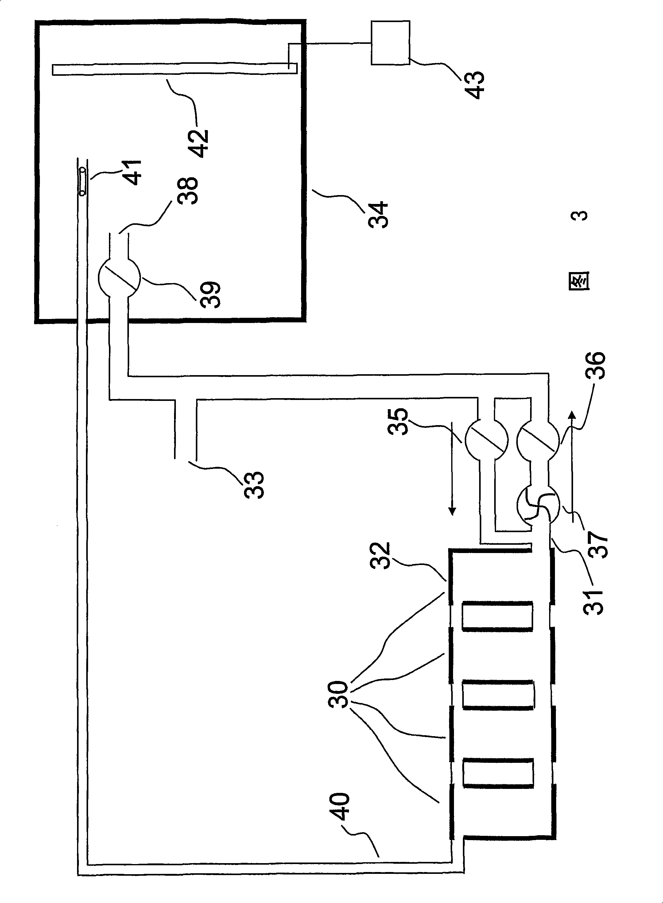
[0045] Embodiments of the present invention provide a fuel system including a non-gauge auxiliary fuel tank and a gauged main fuel tank, and a method of operating an aircraft with such a fuel system.

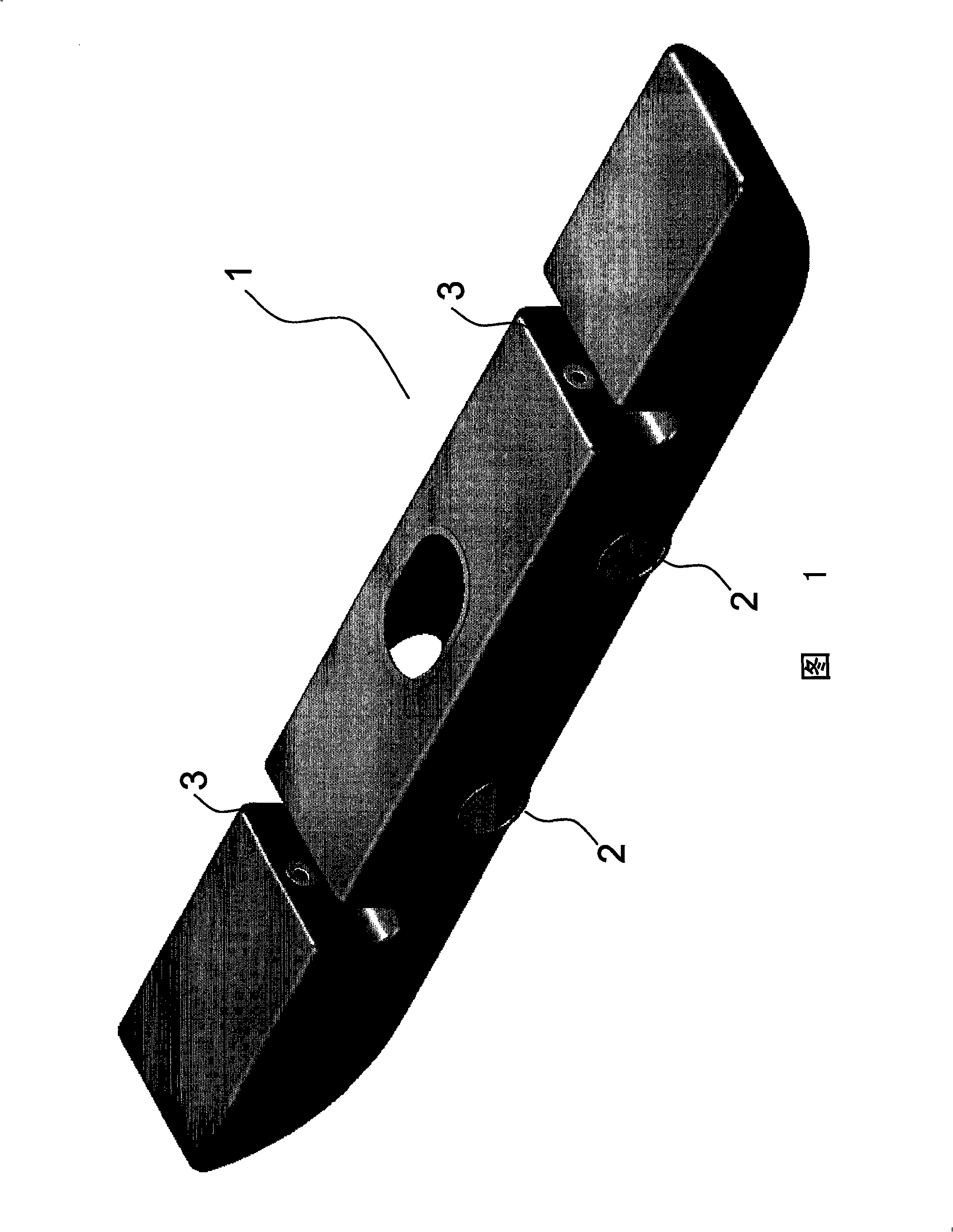
[0046] FIG. 1 shows an auxiliary fuel tank 1 of an embodiment of the present invention. The fuel tank is shaped to fit in an aircraft floor cavity and is provided with interconnecting fittings 2 to allow a plurality of such fuel tanks to be connected together. Vent fittings 3 are provided on top of the fuel tanks to allow air to escape from the tank to ensure complete refueling, the vent connections also serve as overflow outlets for each tank.

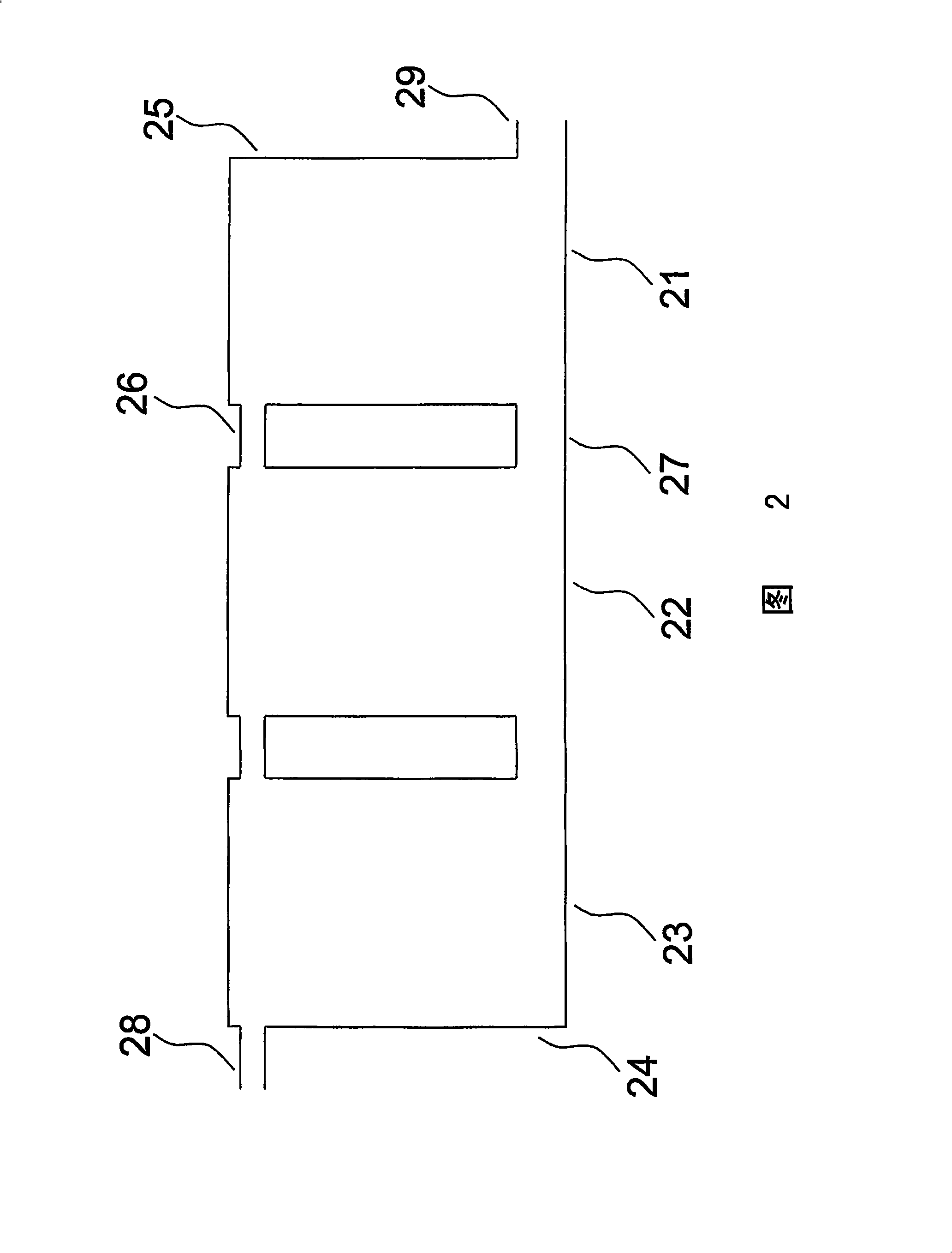
[0047] An auxiliary fuel tank system according to an embodiment of the present invention consists of a plurality of individual fuel tanks connected together by interconnecting and venting fittings. One of the vent fittings is an overflow fitting of the auxiliary fuel tank system and is configured to only allow fuel to escape from the o...


PUM


Abstract

One or more main aircraft fuel tanks (34) are provided with one or more fuel gauges (42) arranged to provide a measure of the amount of fuel in said one or more main fuel tanks. One or more auxiliary fuel tanks (30) are also provided. The aircraft uses fuel during a first phase of fuel consumption, upon commencement of which phase the auxiliary fuel tanks hold fuel. After the first phase said one or more auxiliary fuel tanks (30) are empty and a second phase commences. During the first phase, an indication of the amount of fuel carried by the aircraft is provided by means of summing (i) the amount of fuel in the main fuel tanks (34) as measured by said one or more fuel gauges (42) and (ii) the amount of fuel remaining in said one or more auxiliary fuel tanks (30) as calculated using a measure relating to the fuel consumption rate. During the second phase of fuel consumption, an indication of the amount of fuel carried by the aircraft is provided on the basis of the amount of fuel measured by said one or more fuel gauges (42).

Description

technical field [0001] The present invention relates to an auxiliary fuel tank for an aircraft and a method of monitoring the fuel level when the auxiliary fuel tank is in use. Background technique [0002] Aircraft are usually equipped with fuel tanks located in the wings and center wing boxes. These main fuel tanks are usually permanently fitted to the aircraft and are rigid structures. Main fuel tanks usually include wing tanks and center wing tanks. Multiple fuel gauges are fitted to the main tank so that the amount of fuel remaining in the main tank can be accurately determined, which is important to ensure safe flight. The fuel indicator provides a measurement of the fuel remaining in the tank, which is usually accurate to within 1%. The oil gauge system adopted ensures a highly integrated system with a mean time to failure greater than 1×10 9 Hour. [0003] Auxiliary fuel tanks may be fitted to aircraft to increase fuel capacity and thus increase the range of the...

Claims


Application Information

Patent Timeline
Patent Type & Authority Applications(China)
IPC IPC(8): B64D37/02G01F23/00B60K15/06
CPCB64D37/00G01F9/00G01F23/0076G01F23/804
Inventor F·G·提伯纳K·M·雷
Owner AIRBUS OPERATIONS LTD
Learn More