
Bus-bar casing tube for high-voltage switch cabinet

A high-voltage switchgear and busbar bushing technology, applied in the direction of busbar/line layout, insulators, etc., can solve the problems of wasteful materials, time-consuming inventory, poor versatility, inconvenient installation or assembly, etc. convenient effect

Active Publication Date: 2010-07-28
浙江省开化七一电力器材有限责任公司
View PDF0 Cites 0 Cited by
  • Summary
  • Abstract
  • Description
  • Claims
  • Application Information

AI Technical Summary

Problems solved by technology

This kind of busbar bushing has the following defects in practical application: the busbar fixing plate is integrated with the inner wall of the busbar bushing, and the through hole is also fixed. Therefore, when installing or assembling, because the angle of the metal busbar cannot be adjusted, Not only does it bring a lot of inconvenience to installation or assembly, but also, for switchgears of different series and different current levels, it is necessary to produce corresponding specifications of busbar bushings, which has poor versatility and cannot be adapted to busbars of any specification, and consumes materials, time and inventory.

Method used


Image

  • Bus-bar casing tube for high-voltage switch cabinet
  • Bus-bar casing tube for high-voltage switch cabinet
  • Bus-bar casing tube for high-voltage switch cabinet

Examples


Embodiment Construction

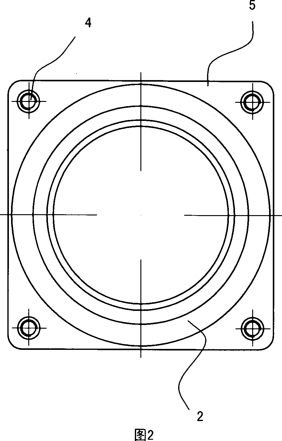
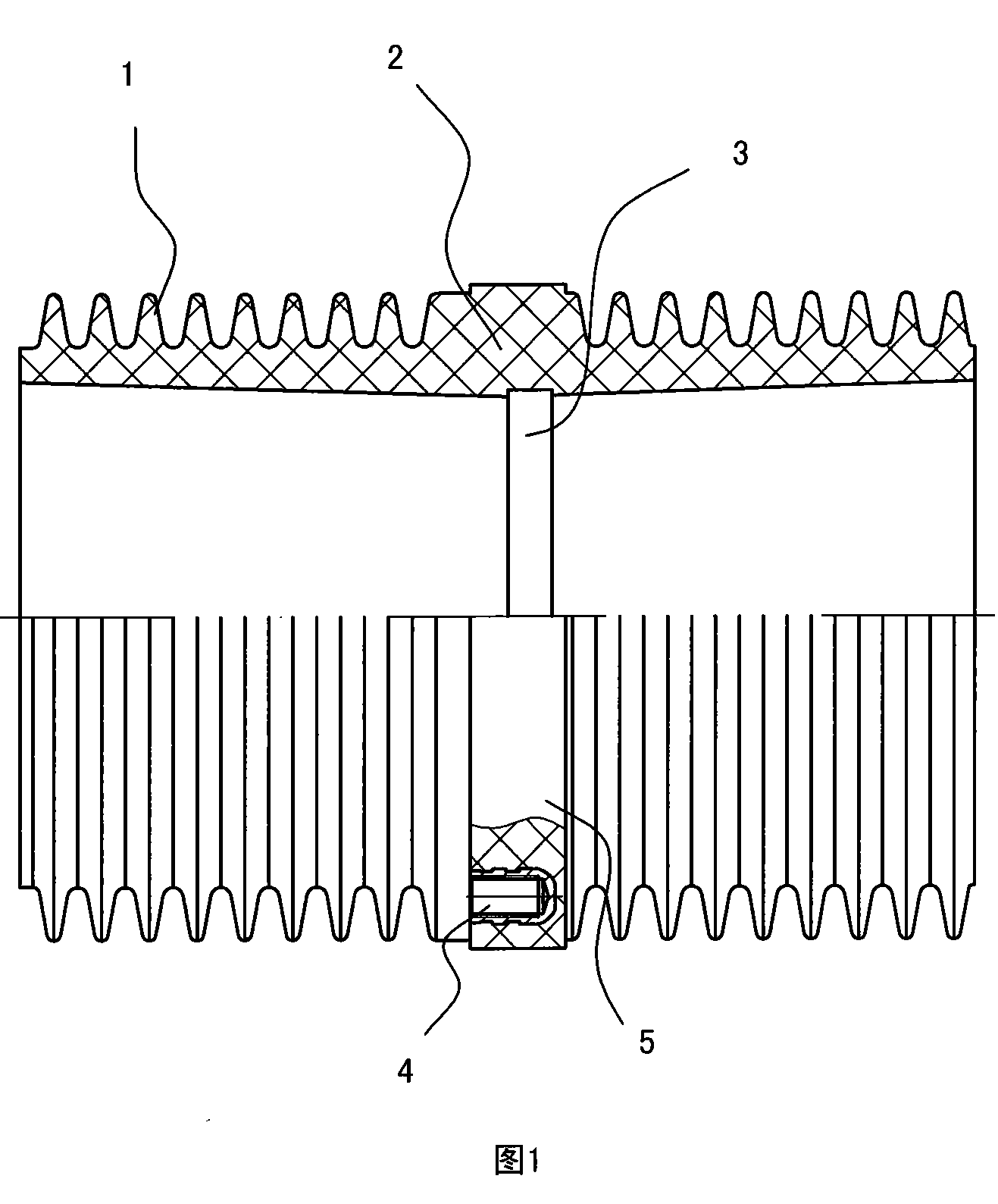
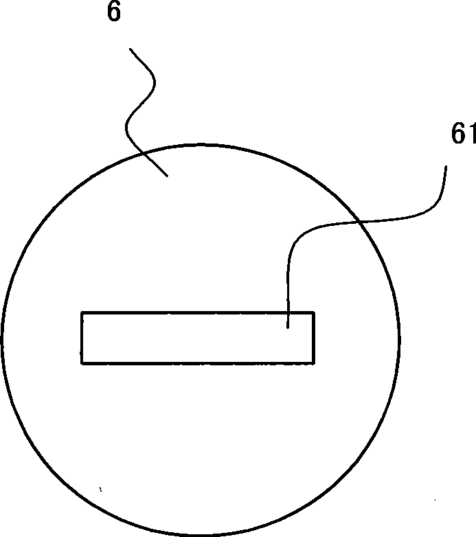
[0012] see figure 1 , and combined with figure 2 . The cross-sectional shape of the insulator 2 is circular, and a plurality of skirts 1 are arranged on its periphery to increase the creepage distance. A radial annular groove 3 is provided on the inner wall of the insulator 2 for receiving the busbar fixing plate 6. The width of the annular groove 3 should match the thickness of the busbar fixing plate 6, and generally a tight fit is better. The inner wall of the insulator 2 is separate from the busbar fixing plate 6, and the circular busbar fixing plate 6 made of silicone rubber material is embedded in the ring groove 3, and the busbar fixing plate 6 can be installed by extrusion.

[0013] The ring groove 3 is arranged in the axial middle of the inner wall of the insulator 2 , so that the metal busbars pass through the through hole 61 to form a balanced shape.


PUM


Abstract

The invention discloses a busbar sleeve which is used in a high voltage switch cabinet. The structure of the busbar sleeve comprises a skirt which is arranged at the external wall of an insulator, and a busbar fixing plate which is radially arranged in an internal channel of the insulator, and the busbar fixing plate is opened with a through hole. The busbar sleeve of the invention is characterized in that: the cross section of the insulator takes the shape of a circular cylinder, the busbar fixing plate and the internal wall of the insulator are segregated, and the circular busbar fixing plate is embedded in an annular groove of the internal wall of the insulator. Compared with the prior art, the busbar fixing plate segregated with the internal wall of the insulator can adjust the angle of the through hole at option by rotating according to requirements, thus achieving the purpose that the metal busbar can be adjusted within 360 degrees along the axial direction of the sleeve, and the use or assembly of the busbar sleeve is very convenient; in addition, an enterprise can respectively process the busbar fixing plate and the insulator, and a selected corresponding busbar fixing plate is assembled in the annular groove of the internal wall of the insulator, thus the user requirement can be met. The busbar sleeve has the advantages of simple improved structure, strong commonalityand remarkable effect.

Description

【Technical field】 [0001] The invention belongs to a busbar bushing used for a high-voltage switch cabinet. 【Background technique】 [0002] For the connection between the high-voltage switchgear and the external main busbar and the connection of the cable inlet and outlet, three insulating bushings should be arranged at intervals on the cabinet wall, and the insulating bushings are generally epoxy resin bushings. The cross-sectional shape of the epoxy resin bushing is elliptical, and there is a skirt on the peripheral wall to increase the creepage distance. A busbar fixing plate is arranged radially on the inner channel of the tube, and the busbar fixing plate is integrated with the inner wall of the bushing. There is a through hole in the middle of the busbar fixing plate. The metal busbar enters the cabinet through the through hole and is accommodated on the inner channel of the bushing. The two ends of the busbar are the connecting ends. This kind of busbar bushing has th...

Claims


Application Information

Patent Timeline
IPC IPC(8): H02B1/20H01B17/58
Inventor 操隆震应兵荣余红英赵侃赵华锋
Owner 浙江省开化七一电力器材有限责任公司
Learn More