Contact system of circuit breaker

A contact system and circuit breaker technology, applied in the directions of circuit breaker contacts, circuit breaker parts, protection switch operation/release mechanisms, etc., can solve the problems of complex structure, spring failure, large resistance, etc., and achieve easy manufacturing and assembly. , Slow down the speed of the fall, the effect of small deformation of the spring

Inactive Publication Date: 2010-08-18
SHANGHAI YONGJI ELECTRICAL HLDG
View PDF1 Cites 0 Cited by
  • Summary
  • Abstract
  • Description
  • Claims
  • Application Information

AI Technical Summary

Problems solved by technology

[0005] After adopting this clamping structure, although the movable contact can be completely blocked when the movable contact is repelled, preventing the movable contact from falling back and playing the role of current limiting protection, there are also the following defects: 1. During the repelling process of the moving contact, the deformation of the contact spring is large, and the spring is overstretched, which may easily cause the spring to fail, and the resistance of the spring acting on the moving contact is relatively large, which is not conducive to the complete repelling of the moving contact. 2. The structure is complex and there are many small parts, which increases the difficulty of manufacturing and assembly

Method used


Image

  • Contact system of circuit breaker
  • Contact system of circuit breaker
  • Contact system of circuit breaker

Examples


Embodiment Construction

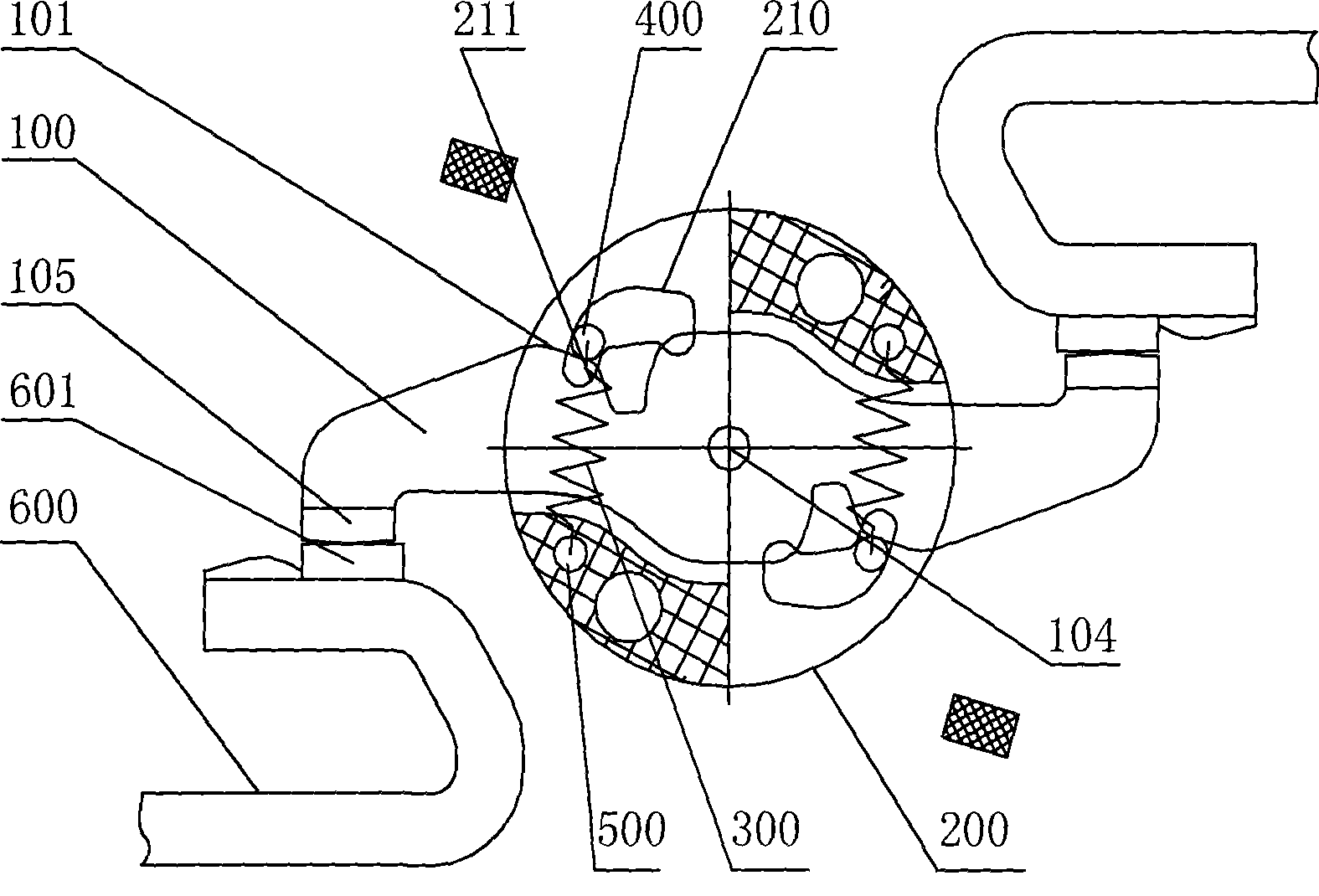
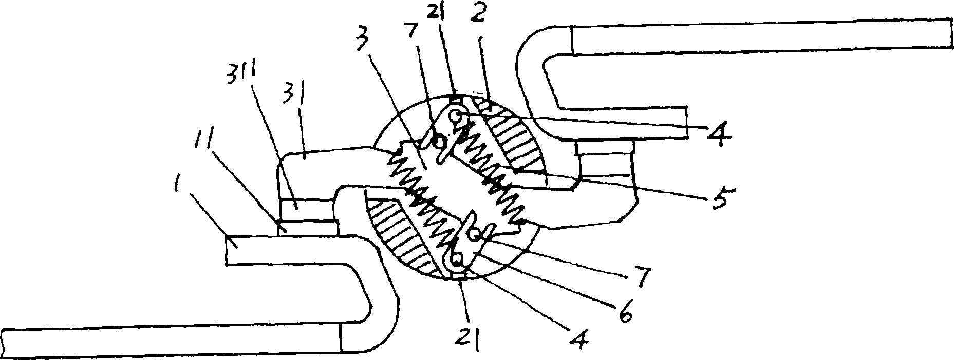
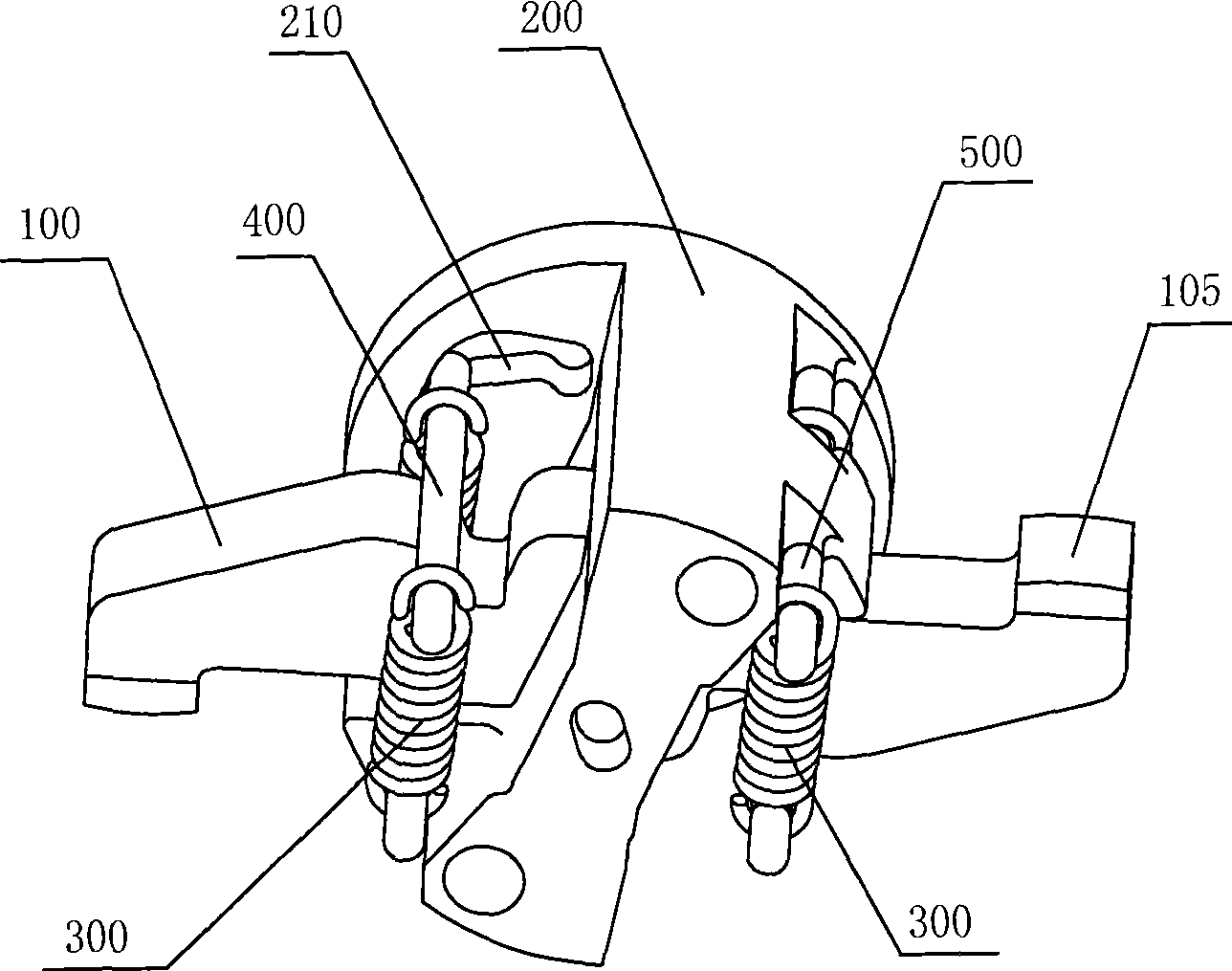
[0021] A circuit breaker double break point contact system of the present invention is shown in Fig. 2, Fig. 3 and Fig. 6. It includes a rotating shaft 200 and a pair of static contact rods 600 with curved parts. The static contact rods 600 are provided with static contacts Point 601 : a moving contact rod 100 passes through the rotating shaft 200 , and the moving contact rod 100 is provided with a central hole 104 , which can be connected to the rotating shaft 200 through a pivot and can rotate in the rotating shaft 200 . A cross-sectional shape of the rotating shaft 200 is shown in Figure 4, two pairs of sliding grooves 210 are symmetrically arranged at its two ends, and each sliding groove 210 includes a first concave portion 211, a second concave portion 212 and a A section of the smooth portion 213 between them is provided with a fixing pin hole 220 at a position opposite to the chute 210 . Both ends of the moving contact bar 100 are provided with a moving contact 105 whi...


PUM


Abstract

The invention discloses a contact terminal system of a breaker, comprising a rotating shaft, a fixed tactile rod, a moving tactile rod and two sliding grooves which are respectively arranged at the two ends of the rotating shaft; each of the sliding grooves comprises a first concave part, a second concave part and a smooth part arranged between the first concave part and the second concave part; a sliding pin is movably arranged in the rotating shaft, and the two ends of the sliding pin are respectively arranged in the two sliding grooves; two springs are arranged at the two sides of the moving tactile rod, and one ends of the springs are connected with the sliding pin in a suspension way, the other ends are fixedly connected with the rotating shaft; a neck is arranged at the back of the moving tactile rod, and the upper edges at the two sides of the neck are respectively connected with a section of driving curved surface and a section of obstructing curved surface; when the moving tactile rod rotates correspondingly to the rotating shaft, the sliding pin can be simultaneously contacted with the driving curved surface of the moving tactile rod and the first concave part of the sliding grooves or be simultaneously contacted with the neck of the moving tactile rod and the second concave part of the sliding grooves. By adopting the contact terminal system, the deformation of the springs is smaller in the process of rejection of the moving tactile rod, thereby being beneficial to the complete rejection of the moving tactile rod.

Description

technical field [0001] The invention relates to a contact system of a circuit breaker. When a large fault current occurs, it can quickly cut off the circuit and ensure that the fault current will not be turned on again, so as to play the role of current limiting protection. Background technique [0002] The contact system of the circuit breaker can connect or break the circuit under the drive of the operating mechanism. At the same time, the circuit breaker is also equipped with a release. When the circuit is overloaded or short-circuited, the release can drive the operating mechanism to make dynamic and static contacts. The head is separated, the circuit is cut off, and it plays a protective role. However, the protective effect of the release is limited, because the action of the release is relatively slow. After the release operates, a series of mechanical transmission processes are required to separate the dynamic and static contacts. For particularly large fault currents...

Claims


Application Information

Patent Timeline
Patent Type & Authority Patents(China)
IPC IPC(8): H01H73/04H01H71/10
Inventor 张晓敏张敏海
Owner SHANGHAI YONGJI ELECTRICAL HLDG
Why Eureka
Try Eureka