Safety protection system for bridge and method thereof

A safety protection and bridge technology, applied in the direction of bridges, bridge parts, bridge construction, etc., can solve problems such as damage, display light box damage, corrosion, etc., to achieve the effect of improving reliability, small force, and preventing damage

Inactive Publication Date: 2009-01-07
深圳市安利交通设施有限公司
View PDF0 Cites 0 Cited by
  • Summary
  • Abstract
  • Description
  • Claims
  • Application Information

AI Technical Summary

Problems solved by technology

[0007] 1. The structure of the display light box is generally difficult to achieve waterproof sealing. In the humid environment of the bridge, especially in the lower installation positions such as bridge columns and piers, and bridges located in coastal areas, due to the influence of ebb and flow, it is easy to cause the display light box The internal structure leaks, so that the internal structure of the display light box is damaged by impregnation and corrosion; if the display light box is manufactured according to the waterproof sealing standard, the cost of the display light box will be greatly increased;
[0008] 2. The display light box is large in size. In typhoon weather, the light box will be subjected to a large thrust due to high wind pressure. This thrust is easy to cause damage to the display light box;
[0009] 3. The display light box is large in size. Installing the display light box on the bridge to display the bridge traffic signs will highlight the shape of the light box and seriously affect the unified coordination of the appearance of the bridge building

Method used


Image

  • Safety protection system for bridge and method thereof
  • Safety protection system for bridge and method thereof
  • Safety protection system for bridge and method thereof

Examples


Embodiment Construction

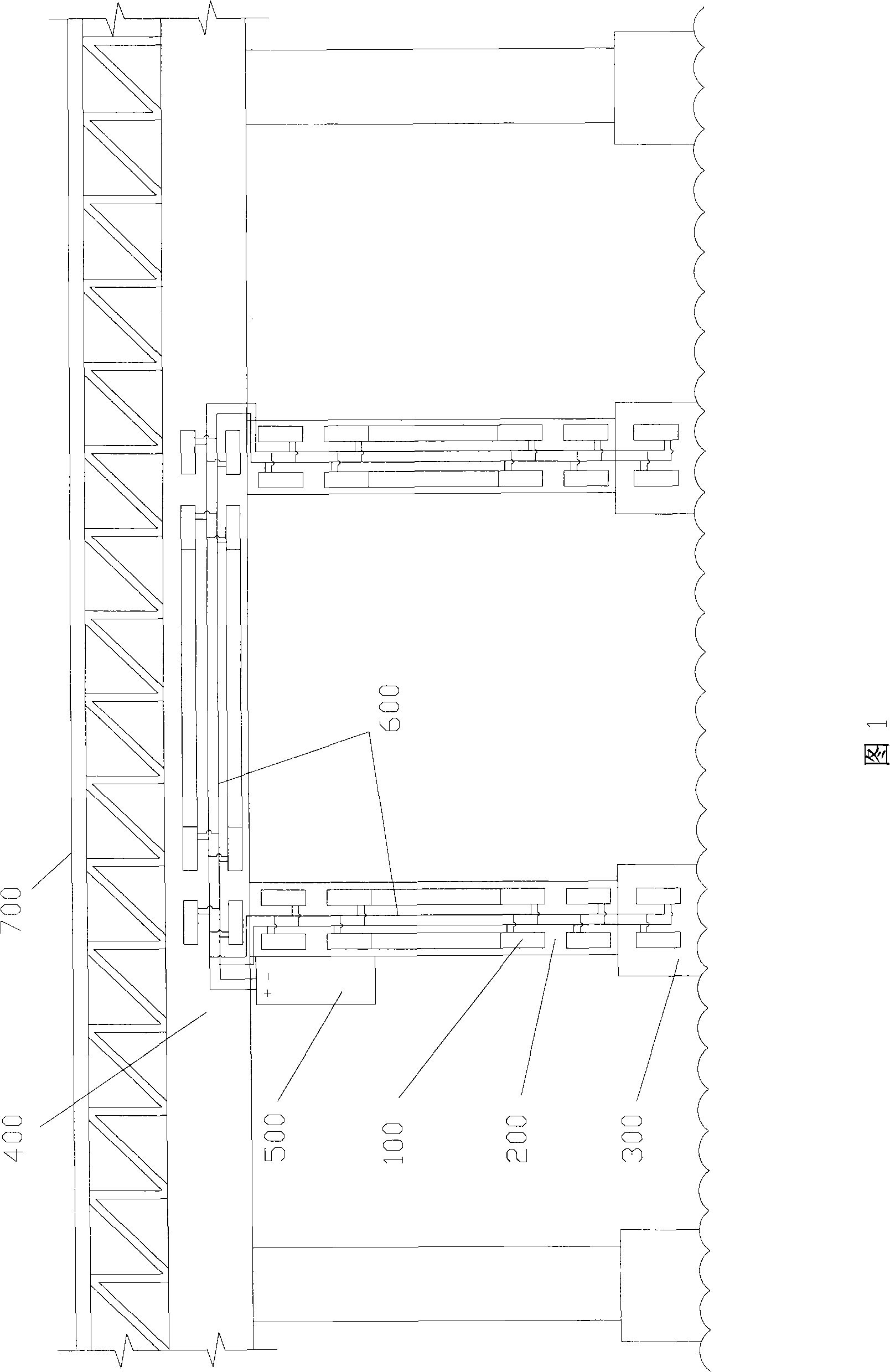
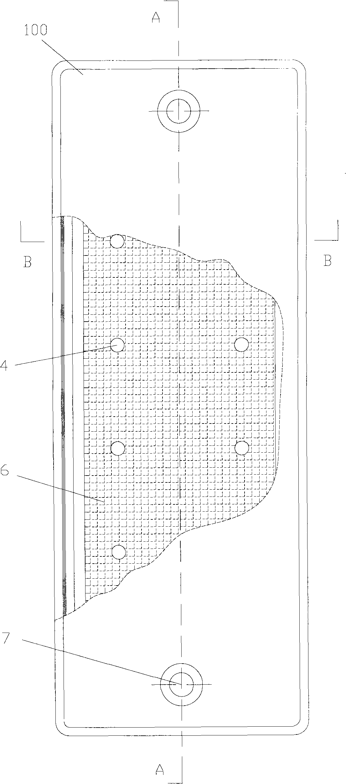
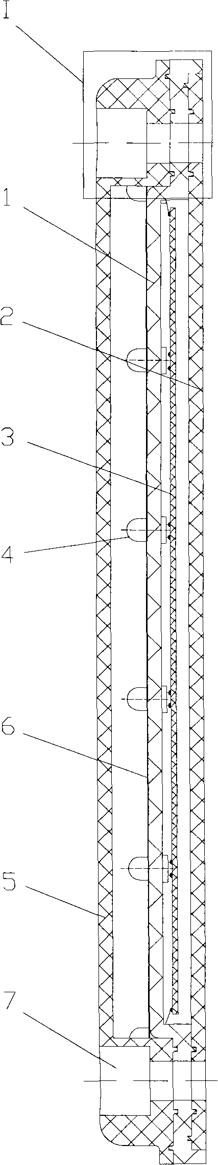
[0032]As shown in Fig. 1 to Fig. 6, the bridge safety protection system of the present invention comprises the luminous induction sign 100 that is arranged on the bridge column 200 on both sides of the waterway, the pier 300 and the bridge body 400 and connects the luminous induction sign 100 by a wire 600. The power controller 500 of the sign 100 (the power controller 500 can be arranged on the bridge body 400, the bridge column 200, the bridge fence 700 or other places), the luminous induction sign 100 includes the sign body 1, and the circuit arranged on the back side of the sign body 1 Board 3, LED light group 4 connected to circuit board 3 through standard body 1, reflective film 6 arranged on the upper side of standard body 1, standard body front cover 5, standard body rear cover 2 and wire 7 connected to circuit board 3 .

[0033] The front cover 5 of the standard body is fastened and connected with the body 1 to form a front cavity space for accommodating the LED lamp ...


PUM


Abstract

The present invention relates to a bridge safety protection system and a method thereof. The system comprises a photo-induced mark arranged on the bridge columns on the two sides of the channel and a power controller; the photo-induced mark comprises a mark body, a circuit board, an LED lamp set, a reflective membrane, a front cover of the mark body, a rear cover of the mark body, a lead and a connecting device for connecting the front cover of the mark body, the mark body and the rear cover of the mark body; the front cover of the mark body is buckled with the mark body to form a front cavity for containing the LED lamp set and the annular matched surface between the front cover of the mark body, and the mark body is provided with a first sealing device; the rear cover of the mark body is buckled with the mark body to form a rear cavity for containing the circuit board and the annular matched surface between the mark rear cover, and the mark body is provided with a second sealing device; the lead penetrates the hole on the rear cover of the mark body and the hole is provided with a seal glue for sealing the hole and the lead. The method sets up the photo-induced mark of the system in the constant brightness display or the flickering display or the combined display of continuous brightness and flickering. The present invention with good sealing and strong wind resistance increases the safety and reliability of the bridge safety protection system without affecting the appearance of the bridge.

Description

technical field [0001] The invention relates to a safety protection system for preventing bridges from being collided by ships, and also relates to a safety protection method of the system, more specifically, to a bridge safety protection system and a method thereof. Background technique [0002] Bridges are important traffic construction facilities, providing roads for land vehicles to cross rivers and greatly promoting land traffic. However, because the bridge piers, bridge columns, bridge body and other structures occupy a certain space in the middle channel of the river, the bridge is convenient for land transportation, but there is a danger of damage to the bridge and the ship caused by the collision of the ship, which affects the safe navigation of the ship. [0003] According to reports, since 1959, there have been nearly 300 ship collision accidents on the main line of the Yangtze River, and the Wuhan Yangtze River Bridge has been hit more than 70 times in the 50 yea...

Claims


Application Information

Patent Timeline
Patent Type & Authority Applications(China)
IPC IPC(8): E01D19/02E01D19/12G08G3/02
Inventor 柯金生周嘉麟陈大路
Owner 深圳市安利交通设施有限公司
Why Eureka
Try Eureka