
Container integrated modularizing pollutant handling arrangement

A pollutant treatment and integrated module technology, applied in anaerobic digestion treatment, waste fuel, etc., can solve the problems of high cost, difficult disassembly and cleaning, and high cost of anaerobic treatment system, and achieve simple, easy and simplified daily operation and maintenance. Design and manufacturing procedures, cost and cycle reduction effects

Inactive Publication Date: 2009-01-07
宋家全
View PDF0 Cites 6 Cited by
  • Summary
  • Abstract
  • Description
  • Claims
  • Application Information

AI Technical Summary

Problems solved by technology

[0007] 1) The cost of establishing an anaerobic treatment system is relatively high, and there is no obvious economic benefit in dealing with pollution sources such as small and medium-sized enterprises, farms and communities;
[0008] 2) Anaerobic treatment systems usually require professionals to design and customize according to local conditions, and professional technical personnel are required to carry out construction, construction and installation, resulting in complex promotion of the system, long time and high cost;
[0009] 3) Conventional anaerobic treatment systems are mostly fixed permanent buildings or facilities. Not only the equipment needs to be designed and manufactured according to the conditions, but also the construction, construction and installation need to be carried out on site
Moreover, when the system is expanded or removed, disassembly and cleaning are also quite difficult and complicated, and require considerable manpower, material and financial resources, reducing the demand for this system

Method used


Image

  • Container integrated modularizing pollutant handling arrangement
  • Container integrated modularizing pollutant handling arrangement
  • Container integrated modularizing pollutant handling arrangement

Examples


Embodiment Construction

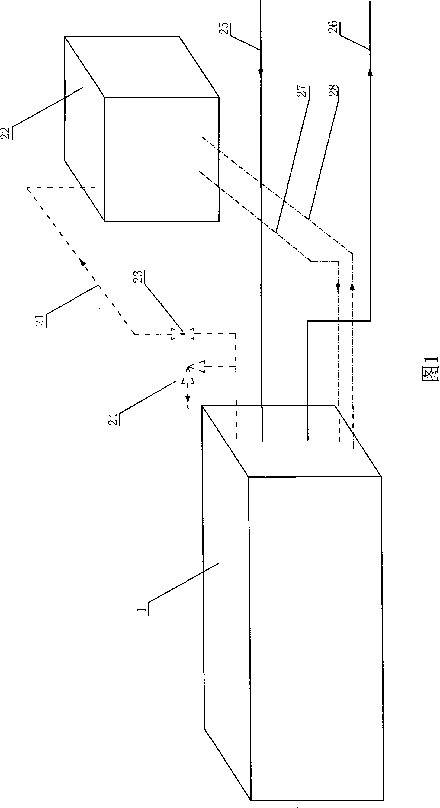
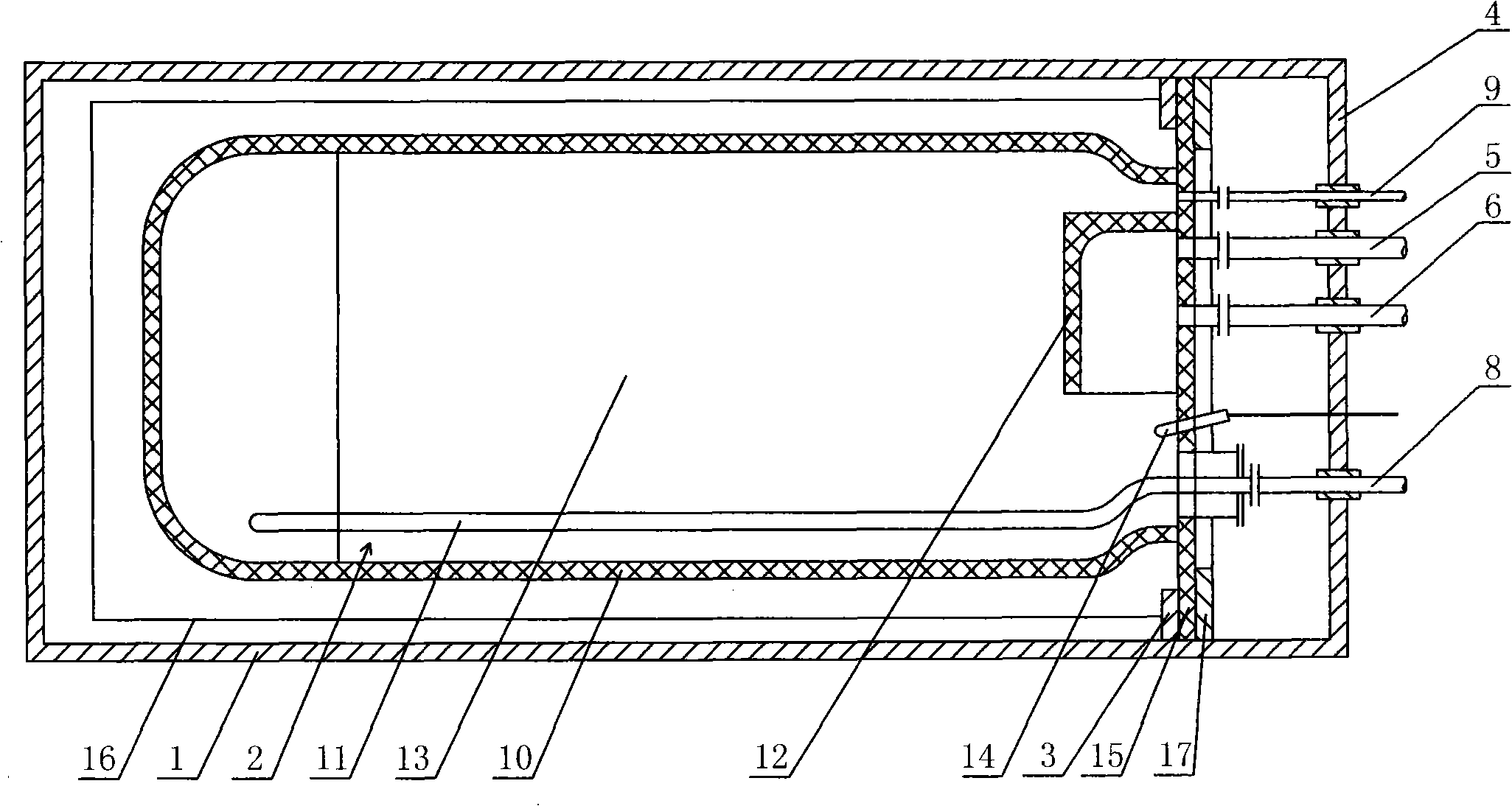
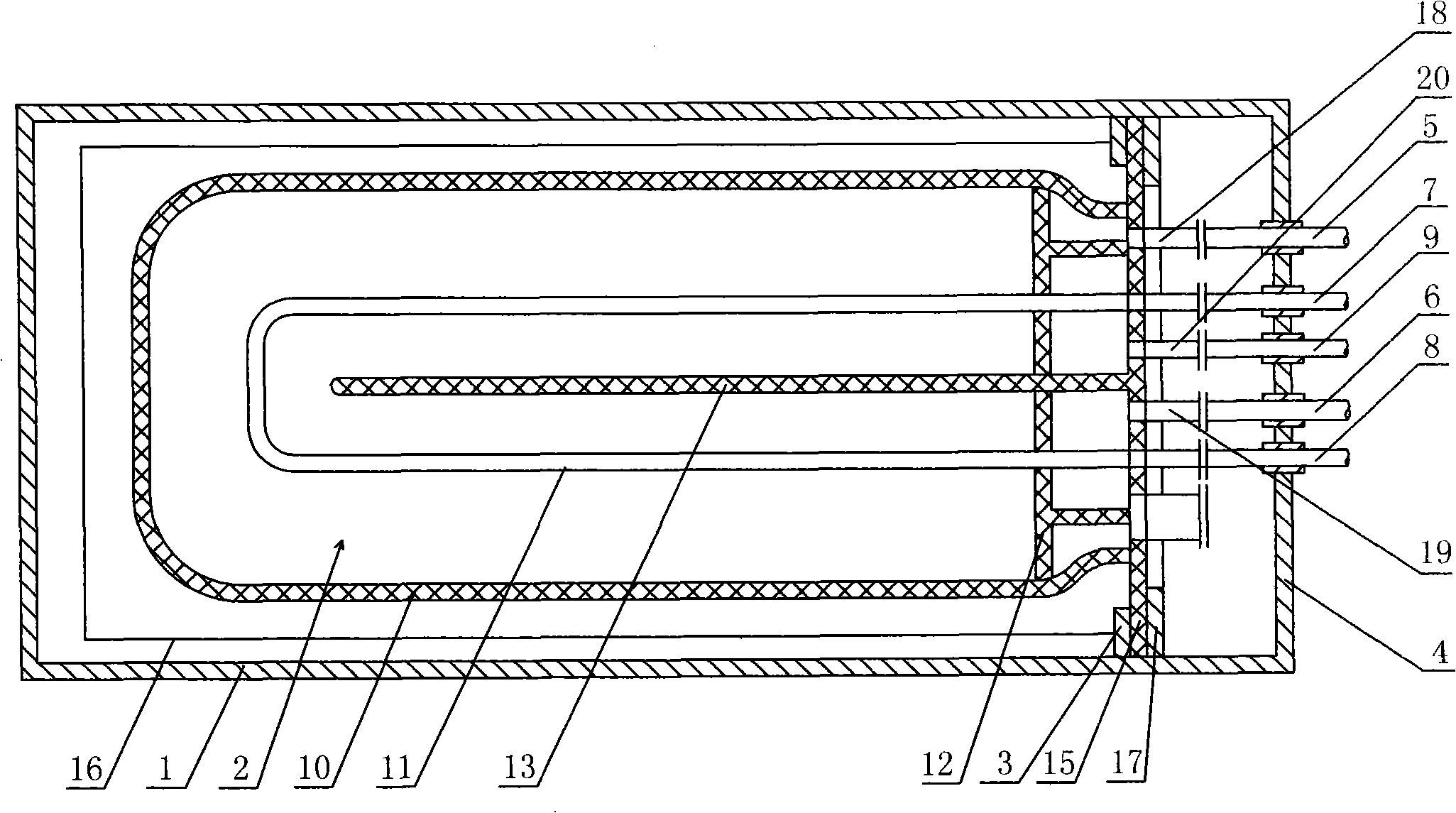
[0032] The container-integrated modular pollutant treatment device is mainly composed of an outer casing 1 and a reactor 2, and the reactor 2 is an anaerobic fermentation reactor.

[0033] The outer shell 1 is a standard container with a length of 6-12m, a width of 1.5-2m, and a height of 1.5-2m. There are fresh material inlet pipe 5, product outlet pipe 6, hot water input pipe 7, return water outlet pipe 8 and methane output pipe 9. The inner wall of the container 1 is lined with a benzene board insulation layer 16 .

[0034] The anaerobic fermentation reactor 2 is arranged in the container 1 . The anaerobic reactor 2 includes a reactor shell 10 , a heating coil 11 , a transverse partition 12 , a vertical partition 13 and a thermocouple 14 . The coiled pipe 11 is a U-shaped pipe.

[0035] The reactor shell 10 is made of rubber, and its volume is adapted to the inner space of the container 1 . There is a skirt 15 at the front of the reactor shell 10, one end of the transve...


PUM


Abstract

The invention relates to an integrated modularized pollutant treatment device for a container, which is mainly composed of a container and a reactor arranged in the container. A heating coil pipe, a transversal baffle plate, a longitudinal baffle plate and a thermoelectric couple are arranged at the bottom of the reactor. Both ends of the heating coil pipe are respectively connected with a hot water inlet pipe and a backwater outlet pipe on the front end face of the container. A fresh material input pipe, an outcome overflowing outlet pipe and a marsh gas outlet pipe are further arranged on the front end face of the reactor, and are respectively and fixedly connected with a fresh material inlet pipe, an outcome outlet pipe and the marsh gas outlet pipe on the front end face of the reactor through a flange. The modularized design requires no special manufacture design, thereby simplifying the procedures of design and manufacture, carrying out mass production, reducing the cost and the cycle of a system, and improving the economic benefit of the using system, so that the system is very compact; not only the land use area is saved greatly, but also the materials and a process pipeline, as well as the design and the demands of public works can be simplified.

Description

technical field [0001] The invention relates to a pollutant treatment device for improving the living environment of human beings, in particular to a container-integrated modular pollutant treatment device. Background technique [0002] With the rapid development of industrial and agricultural production and the rapid improvement of people's living standards, the discharge of pollutants is increasing day by day. In industry, agriculture and daily life, a large amount of pollutants with high organic content will be produced, such as sludge slurry and sewage pollutants, such as sludge or wastewater produced by papermaking, textile, food industry, sewage and sludge produced by human daily life As well as a large amount of animal manure and abandoned agricultural products from livestock produced by agricultural and animal husbandry. Direct discharge of these pollutants without treatment will seriously reduce water quality and air quality and will endanger the health of human be...

Claims


Application Information

Patent Timeline
Patent Type & Authority Applications(China)
IPC IPC(8): C02F3/28
CPCY02E50/343Y02E50/30
Inventor 宋家全
Owner 宋家全
Learn More