
Processor, test tray transfer method and package chip manufacture method

A technology for testing trays and installing chips, which is applied in the field of processors and can solve problems such as control operation errors

Active Publication Date: 2008-12-31
MIRAE CORPORATION
View PDF0 Cites 8 Cited by
  • Summary
  • Abstract
  • Description
  • Claims
  • Application Information

AI Technical Summary

Problems solved by technology

[0021] First, failure of a major component (e.g., pick-up) during one operation prevents the continuation of another operation
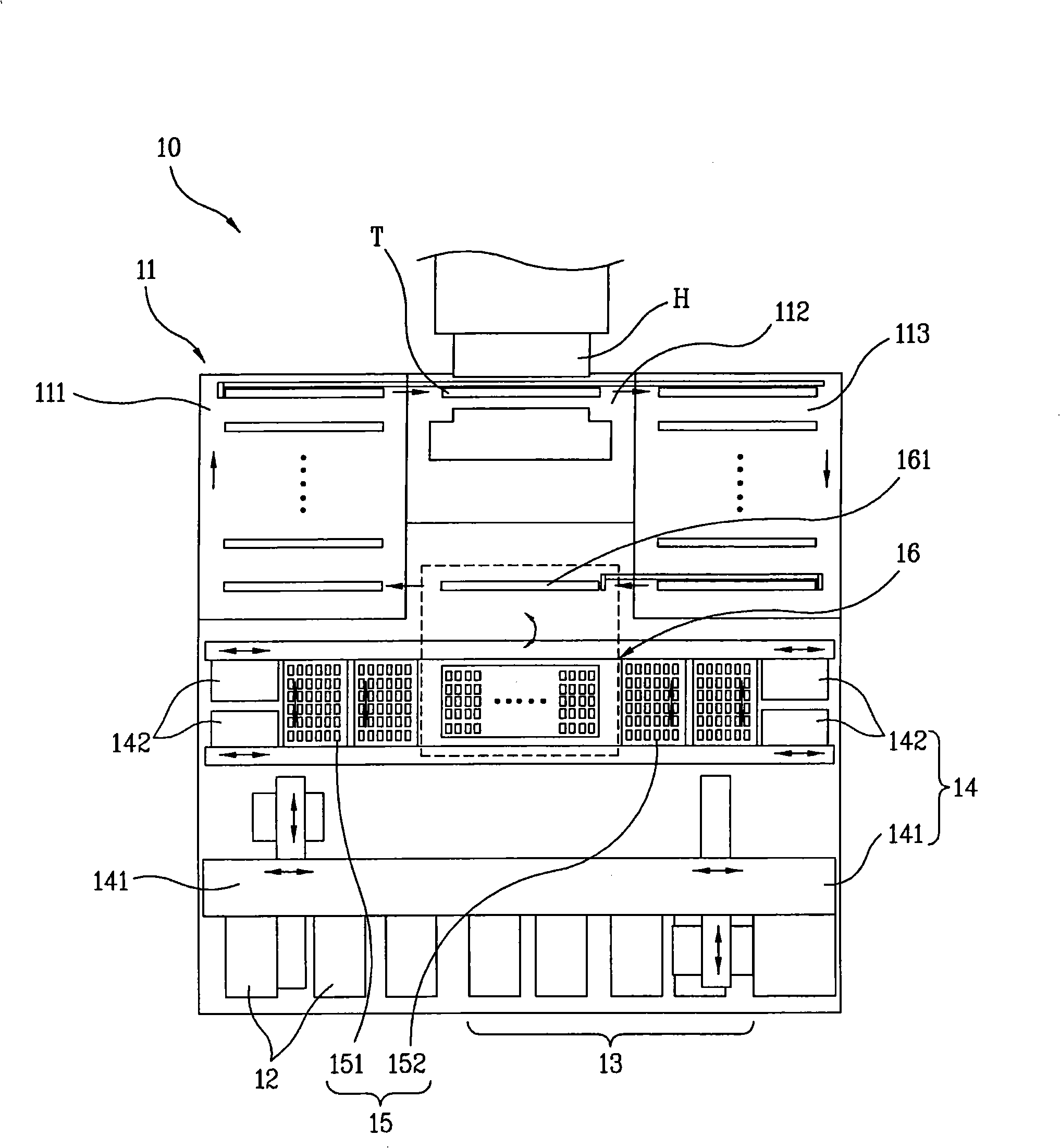
[0022] Secondly, due to the complicated procedure of simultaneously unloading packaged chips intended for electrical testing from the test tray and loading the packaged chips into the test tray, errors often occurred in the control operations of the first and second pickers

Method used


Image

  • Processor, test tray transfer method and package chip manufacture method
  • Processor, test tray transfer method and package chip manufacture method
  • Processor, test tray transfer method and package chip manufacture method

Examples


Embodiment Construction

[0040] Reference will now be made in detail to the preferred embodiments of the present invention, examples of which are illustrated in the accompanying drawings.

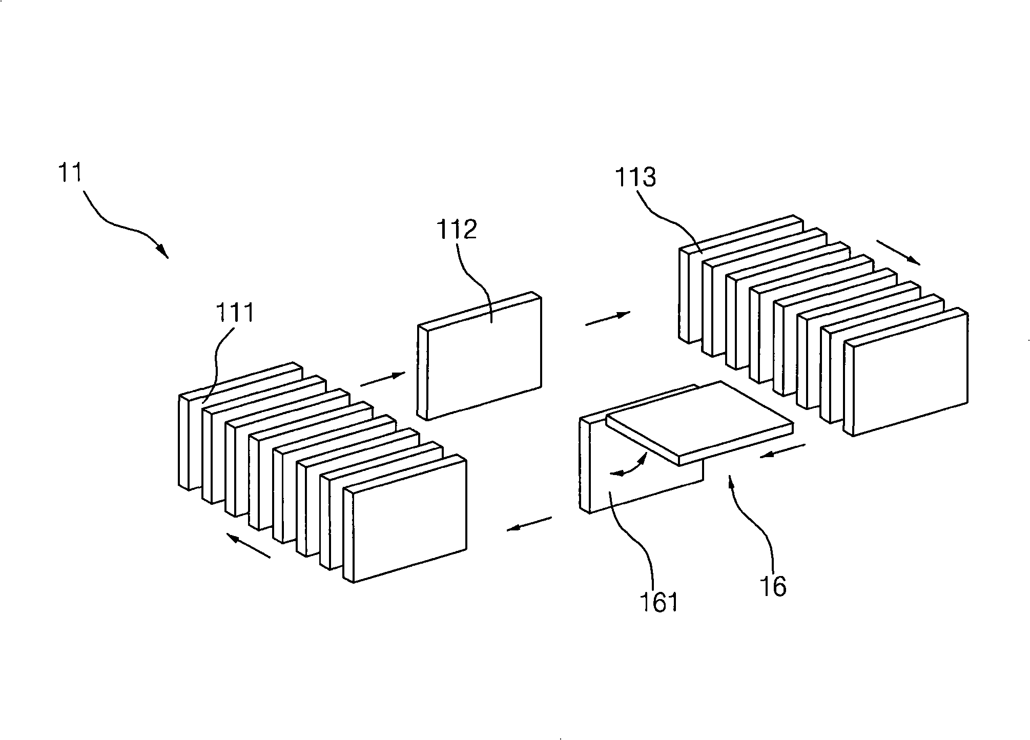
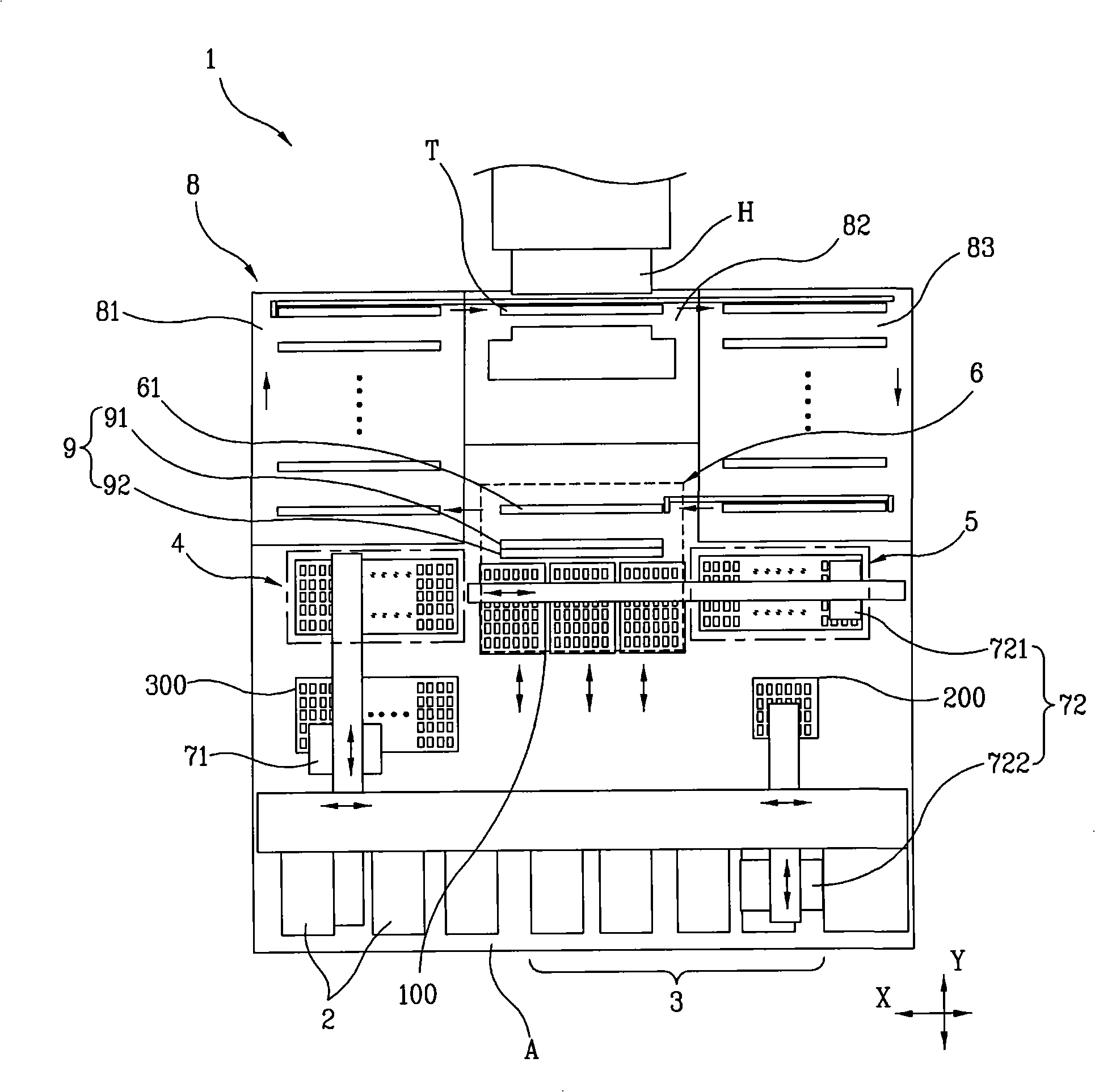
[0041] image 3 It is a plan view of the structure of the processor used in the present invention. Figure 4 is a schematic diagram of the test tray path between the loading unit and the unloading unit in the handler. Figure 5 is a schematic diagram of the path of the test tray inside the chamber of the first embodiment of the present invention. Image 6 is a schematic diagram of the path of the test tray inside the chamber of the second embodiment of the present invention. Figure 7 is a plan view of the handler illustrating the path along which the test tray is moved from the unloading position to the loading position.

[0042] like image 3 As shown, the handler 1 of the present invention includes a loading stacker 2, an unloading stacker 3, a loading unit 4, an unloading unit 5, a rotating unit 6, a picker...


PUM


Abstract

The invention relates to a handler having structure which includes a loading position at which packaged chips are loaded into a test tray, and an unloading position at which the packaged chips are unloaded from the test tray. The test tray follows a path through the handler from the loading position to the unloading position, and from the unloading position to the loading position. By separately performing the loading and unloading operations at these different positions within the handler, malfunctions in loading and unloading pickers that load and unload the chips may be reduced. Further, amalfunction in one picker performing one operation may be prevented from influencing operations of the other picker performing another operation. Additionally, collision between the loading picker and the unloading picker may be prevented.

Description

technical field [0001] The present invention relates to a handler, a method for transferring a test tray containing packaged chips for the handler, and a method for manufacturing packaged chips for use in the handler. Background technique [0002] A handler for passing packaged chips through electrical testing after the packaging process is complete. [0003] The handler transfers the packaged chips from the user tray to the test tray, and supplies the test tray containing the packaged chips to the tester. The tester includes a test board with many sockets. The handler brings the packaged chips in the test tray into contact with the sockets of the test board, respectively. The tester then performs electrical testing on the packaged chip. After grading the packaged chips according to the test results, the handler transfers them from the test tray to the corresponding user tray. [0004] The handler includes first, second and third chambers. In the first chamber, the pack...

Claims


Application Information

Patent Timeline
Patent Type & Authority Applications(China)
IPC IPC(8): G01R31/28G01R1/02
CPCG01R31/2893H01L21/68
Inventor 安正旭朴海俊玄炅珉崔完凞
Owner MIRAE CORPORATION
Learn More