
Novel door closer

A door closer, a new type of technology, applied in the direction of wing closers, door/window accessories, wing openers, etc., can solve the problems of high consumption of raw materials, visual barriers, low concealment, etc., to achieve flexible installation positions and visual barriers Small size, the effect of saving raw materials

Inactive Publication Date: 2008-12-31
崔惠鹏
View PDF0 Cites 2 Cited by
  • Summary
  • Abstract
  • Description
  • Claims
  • Application Information

AI Technical Summary

Problems solved by technology

This door closer has the following disadvantages: first, it can only make the door close automatically, and cannot keep the door in the open position when it is opened to a certain angle (referring to the angle between the door and the upper and lower sides of the door frame).
Because sometimes, users want the door to remain open when the door is opened to a larger angle; second, the structure is complex, involving hydraulic pressure, piston, force arm, spring and other technologies and components, and consumes a lot of raw materials; third , it needs to be connected and fixed on both the door and the door frame
Punch holes in the door and cause damage; fourth, it can only be installed on the top of the door, and the installation position is not flexible; fifth, the concealment is low, causing visual obstacles

Method used


Image

  • Novel door closer
  • Novel door closer
  • Novel door closer

Examples


Embodiment Construction

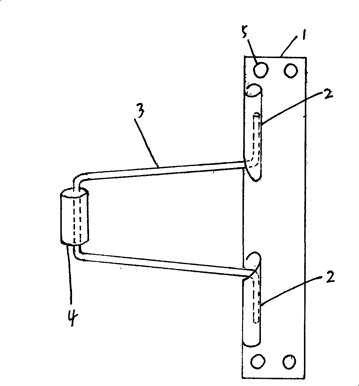
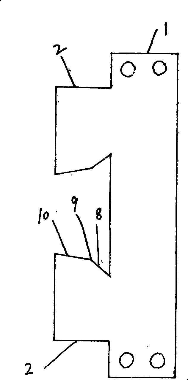
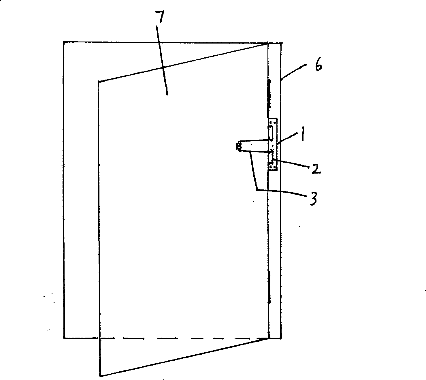
[0013] In this embodiment, it is assumed that the door opens counterclockwise from left to right. figure 1 Among them, the state of the new door closer is that the door is in the closed position, which is the natural state of the new door closer. There are screw holes (5) at the four corners of the vertical plate (1), and there is a card slot (2) with a circular section on the side of the vertical plate (1) close to the door shaft. The card slot (2) is divided into upper and lower parts. The two parts are symmetrical up and down. The card slot (2) is formed by extending, curling and cutting the side edge of the vertical plate (1) close to the door shaft. The upper edge of the upper part of the card slot (2) is flat, the lower edge is inclined, and the slope of the first half of the lower edge is greater than the slope of the second half. The shape of the lower part of the card slot (2) is axisymmetric to that of the upper part. The two ends of the bent elastic steel wire (3...


PUM


Abstract

Disclosed is a new door closer which belongs to the mechanical field and is used for solving the defects of being unable to make the door maintain the opening state when the door is opened to a certain degree, complicated structure and bad concealment property found in the door closer in the prior art; the new door closer can enable the door to be closed automatically when the door is opened less than a certain angle and enables the door to be maintained in the opening state when the door is opened more than the angle; the new door closer is mounted on the inner side of the vertical door frame on the door shaft; a clamp groove composed of an upper part and a lower part is fixed on one side of a vertical flat plate; both ends of an elastic steel wire bent to be U-shaped are folded outwards to be arranged in the upper and lower parts of the clamp groove. The edge of the clamp groove contacted with the elastic steel wire is inclined; the elastic steel wire is enabled to have vertical compression deformation through the pressing force of the clamp groove inclined edge when the door is opened through the rotation in the horizontal direction; the deformation enables the elastic steel wire to generate the door closing force in the horizontal direction; the door closing force is reduced when the elastic steel wire rotates to the position through the reduction of the gradient of the back segment of the clamp groove inclined edge so that the door is maintained in the open state.

Description

technical field [0001] The invention is a novel door closer installed on a door and window structure. It can make the door close automatically, or it can keep the door open when it is opened to a certain extent. Background technique [0002] At present, the commonly used door closers are all installed on the top of the door, and the door and the door frame are connected by a force arm, which generates elastic force through the deformation of the spring, and then acts on the door through the force arm to automatically close the door. This door closer has the following shortcoming: the first, can only make the door close automatically, can not make the door when opening to a certain angle (referring to the included angle of door and door frame upper and lower sides), remain in the open position. Because sometimes, users want the door to remain open when the door is opened to a larger angle; second, the structure is complex, involving hydraulic pressure, piston, force arm, spr...

Claims


Application Information

Patent Timeline
IPC IPC(8): E05F1/12
Inventor 崔惠鹏
Owner 崔惠鹏
Learn More