Pulse laser forming method and device of thin-wall corrugated tube

A technology of pulsed laser and bellows, applied in laser welding equipment, metal processing equipment, welding equipment, etc., to achieve the effects of large processing flexibility, improved fatigue life, and high processing efficiency

Inactive Publication Date: 2011-04-20
SHANDONG UNIV
View PDF5 Cites 0 Cited by
  • Summary
  • Abstract
  • Description
  • Claims
  • Application Information

AI Technical Summary

Problems solved by technology

Due to the liquid filling in the pipe, it is not easy to control when forming small corrugated pipes; rolling forming relies on the forming wheel in the pipe for rolling, and is mainly used for processing large corrugated pipes; mechanical bulging adopts expansion inside the pipe This method is not suitable for the manufacture of tiny corrugated pipes; for corrugated pipes with excessive wave height or special waveforms, welding is often used, but this kind of corrugated pipes cannot withstand internal pressure. The scope of application is limited; deposition forming is to use the electrodeposition method to deposit the bellows material on the mandrel, and then ablate the mandrel. This method is suitable for the manufacture of tiny bellows (such as the minimum inner diameter can reach 0.75mm, and the minimum length can reach 1mm), but the cost is too high and currently limited to nickel
Since fatigue damage is usually a common way of corrugated pipe damage, but the above-mentioned methods are difficult to exert the anti-fatigue ability of the material; in addition, with the development of the micro-electromechanical (micro sensor, etc.) industry, the demand for tiny bellows is increasing Therefore, there is an urgent need for a method and device for manufacturing micro bellows with high efficiency, wide process range, easy operation and control, and high fatigue life.

Method used


Image

  • Pulse laser forming method and device of thin-wall corrugated tube
  • Pulse laser forming method and device of thin-wall corrugated tube
  • Pulse laser forming method and device of thin-wall corrugated tube

Examples


Embodiment Construction

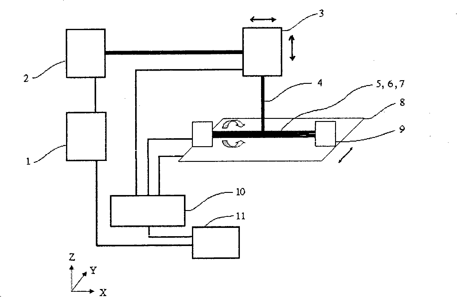
[0029] The energy size, laser mode, pulse width, pulse frequency, and pulse number of the laser beam 4 are regulated and controlled by the laser generator control system 1 . The spot diameter of the laser beam is adjusted by moving the laser head 3 in the Z direction and controlled by the motion control system 10 . The motion control system 10 simultaneously controls the movement of the laser head 3 in the X direction, the movement of the worktable 8 in the Y direction, and the rotation of the small chuck 9 on the worktable 8 . The movement in each direction makes the workpiece system and the laser beam 4 move relative to each other at a predetermined speed and trajectory through interpolation, so as to perform multi-point impact in an orderly manner.

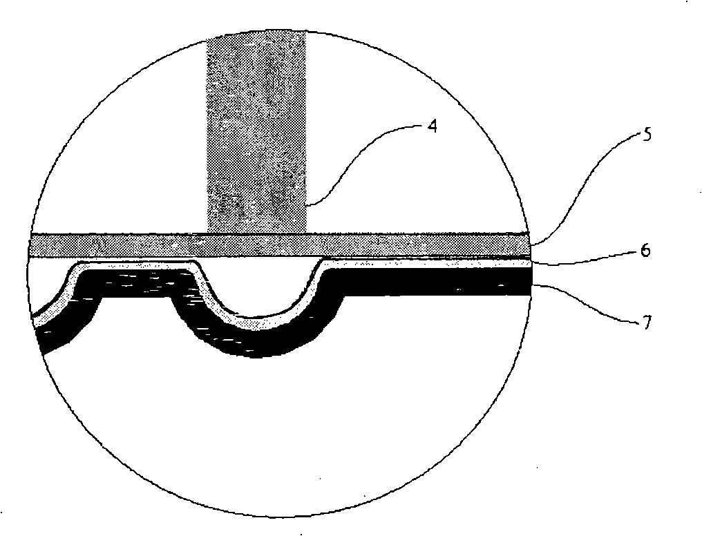
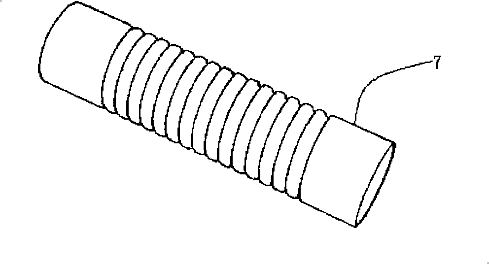
[0030] figure 2 yes figure 1 A partial cross-sectional schematic diagram of the workpiece system in the medium, which includes a constrained layer 5, an energy absorbing layer 6, and a pipe 7, and the energy absorbing layer...


PUM

PropertyMeasurementUnit
thicknessaaaaaaaaaa
thicknessaaaaaaaaaa
thicknessaaaaaaaaaa

Abstract

The invention discloses a pulsed laser forming method of a thin-walled corrugated tube and a special device for realizing the method. The method comprises the following steps: a pulsed laser beam 4 acts on an energy absorbing layer 6 covered on the surface of a thin-walled tube 7 so as to produce plasma cloud; the plasma cloud further absorbs laser energy and explode, the detonation wave thus produced causes impact force facing the tube wall under the action of a bushing 5 of a restraint layer, and the thin-walled tube 7 is machined into a corrugated tube by virtue of the axial translation and rotation of the thin-walled tube 7. The special device for realizing the method is composed of a laser generator system, a laser head system, a workpiece system, a workbench system and a motion control system. By the method, the metal and alloy materials made from steel, aluminum, copper and the like can be machined, and the non-metallic materials such as silicon and the like can also be machined. The method is especially suitable for manufacturing parts of micro electromechanical systems such as a micro sensor, a micro compensator and a micro connector.

Description

technical field [0001] The invention relates to a pulse laser forming method for a thin-wall corrugated pipe and a special device for realizing the method. Background technique [0002] Bellows are widely used. As elastic elements, they can be used for sensitive elements, compensation elements, connectors and seals of various measurement, adjustment, control, and sensing instruments; as flexible sections of expansion joints, they can be used for compensation pipelines Axial, lateral and angular displacements caused by temperature differences can also be used in pipelines to compensate for positional deviations and absorb vibrations of piping systems. Since bellows are usually subjected to alternating loads, high fatigue resistance is often required. [0003] There are many forming methods for bellows, such as hydroforming, roll forming, mechanical bulging, welding forming and deposition forming. Among them, hydroforming is the most common, which uses the liquid pressure i...

Claims


Application Information

Patent Timeline
Patent Type & Authority Patents(China)
IPC IPC(8): B23K26/18B23K26/00
Inventor 季忠刘韧王巍刘晓军张明浩林乐嘉
Owner SHANDONG UNIV
Why Eureka
Try Eureka