Tri-state overrunning clutch

An overrunning clutch, outer ring technology, applied in clutches, one-way clutches, mechanical equipment, etc., can solve problems such as affecting service life, heat generation, and wear and tear

Active Publication Date: 2008-12-24
BYD CO LTD
View PDF2 Cites 9 Cited by
  • Summary
  • Abstract
  • Description
  • Claims
  • Application Information

AI Technical Summary

Problems solved by technology

[0004] However, in the existing overrunning clutches, the overrunning state and wedging state of the overrunning clutch are realized through the relative rotation between the inner and outer rings, and the clutch itself has no additional mechanism to control the working position of the sprags, so there are The problem is that the overrunning clutch only has a one-way overrunning state and a one-way wedging state, and has a single function
In some specific construction machinery applications

Method used


Image

  • Tri-state overrunning clutch
  • Tri-state overrunning clutch
  • Tri-state overrunning clutch

Examples


Embodiment Construction

[0018] Specific embodiments of the present invention will be described in detail below with reference to the accompanying drawings.

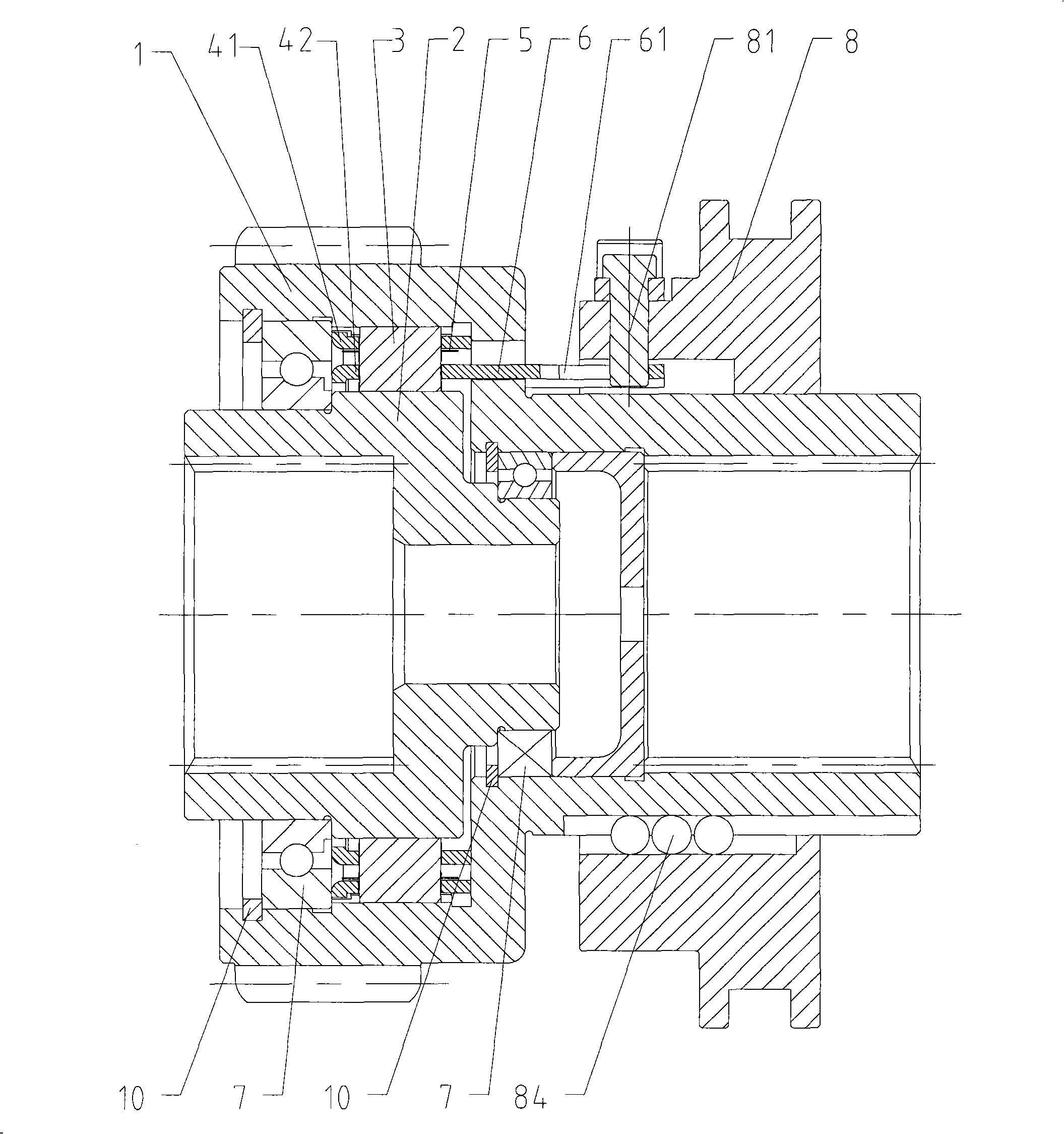
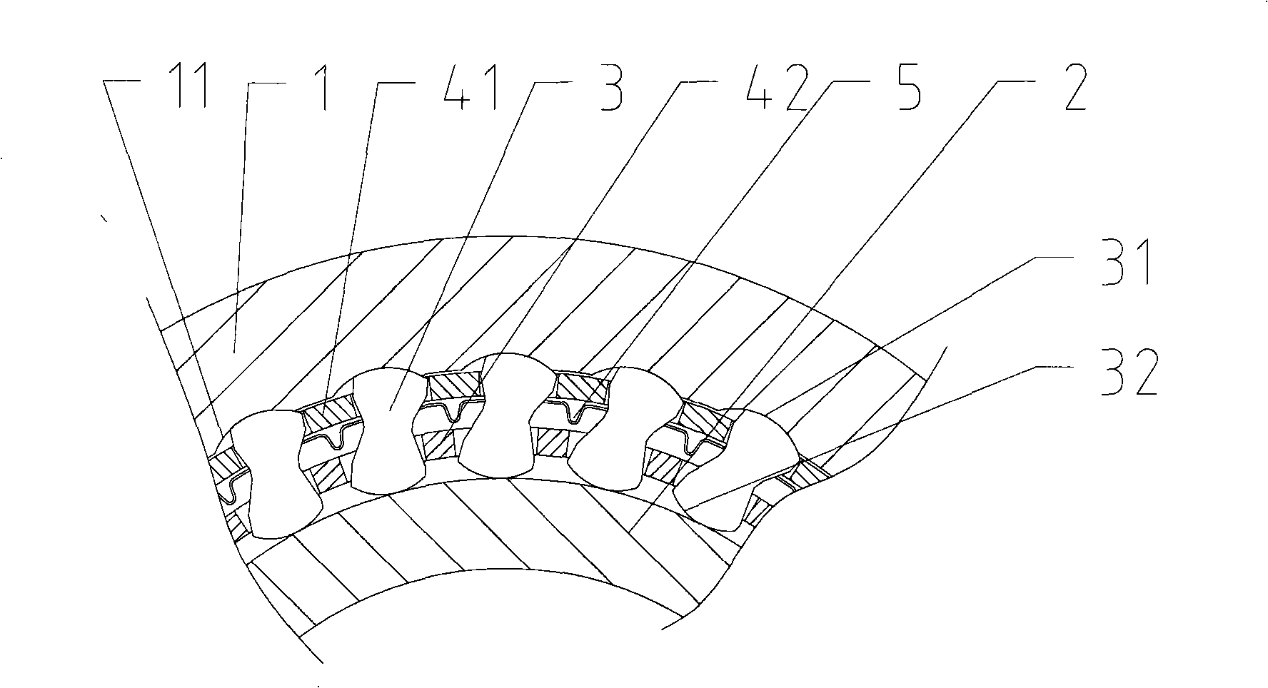
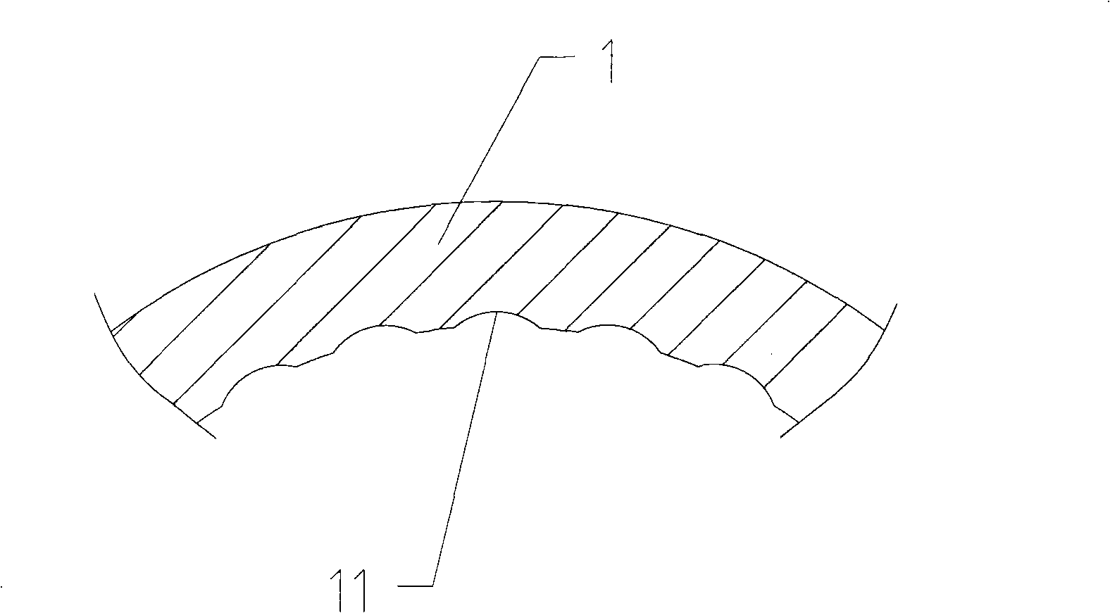
[0019] As shown in the figure, a three-state overrunning clutch provided by the present invention includes an outer ring 1, an inner ring 2, a plurality of sprags 3 located between the outer ring 1 and the inner ring 2, and a plurality of sprags 3 located between the outer ring 1 and the inner ring 2. The outer holder 41 and the inner holder 42 of the plurality of wedges 3 are held between them and for example through holding holes. There are a plurality of arc grooves 11 on the working surface of the outer ring 1, and each arc groove 11 cooperates with a working surface 31 of a corresponding wedge 3, and keeps the working surface 31 on the circle. In the arc groove 11. The inner cage 42 has a plurality of protrusions 6 protruding axially outward, and each protrusion 6 has an oblique hole 61 inclined relative to the axial direction. An axially...


PUM


Abstract

The invention provides a tristate superior clutch, which comprises an outer ring, an inner ring, a plurality of wedgy blocks positioned between the outer ring and the inner ring and an outer retaining frame and an inner retaining frame which are positioned between the outer ring and inner ring and used for retaining the blocks. A plurality of circular arc grooves are arranged on a working face of the outer ring; each circular arc groove is matched with a working face of the corresponding wedgy block and retains the working face in the circular arc groove. The inner retaining frame is provided with a plurality of convex plates which extend outwards along the axial direction; each convex plate is provided with an oblique hole which is oblique corresponding to the axial direction. A poking disc which can slide in the axial direction is arranged on the peripheral surface of the outer ring; a plurality of poke rods which are respectively inserted into the corresponding oblique hole are fixed on the poking disc. Through moving the poke rods of the poking disc to control the wedgy blocks to fully leave a working face of the inner ring, the outer ring and the inner ring can freely rotate in a positive direction and a negative direction, thereby obtaining a bidirectional separation working state of the tristate superior clutch.

Description

technical field [0001] The invention relates to an overrunning clutch, in particular to a three-state overrunning clutch, which can control the inner ring and the outer ring of the overrunning clutch to be completely disengaged from each other so as to freely rotate in forward and reverse directions. Background technique [0002] An overrunning clutch, also known as a one-way clutch or a one-way bearing, is a device that can only transmit torque in one direction of rotation. Existing overrunning clutches mainly include roller type overrunning clutches and sprag type overrunning clutches. [0003] As an example of a sprag type overrunning clutch, CN 2476675Y (or CN 1430000A) discloses a kind of overrunning clutch with double cages, the overrunning clutch includes an inner ring and an outer ring, and a plurality of Wedges, and these wedges are held by the holding holes opened in the double cage (including the inner cage and the outer cage) between the inner and outer rings. ...

Claims


Application Information

Patent Timeline
IPC IPC(8): F16D41/063
Inventor 任毅杨胜麟郭松岳
Owner BYD CO LTD
Why Eureka
Try Eureka