
Method for transferring a micron pattern on an optical pattern and the thus obtained optical pattern

A micron-scale, patterned technology that is used in the field of optical articles, optical lens type products, and spectacle lens types

Active Publication Date: 2011-05-25
ESSILOR INT CIE GEN DOPTIQUE
View PDF4 Cites 2 Cited by
  • Summary
  • Abstract
  • Description
  • Claims
  • Application Information

AI Technical Summary

Problems solved by technology

However, this process makes it difficult to confine the metal layer to the portion of the surface occupied by the hologram

Method used


Image

  • Method for transferring a micron pattern on an optical pattern and the thus obtained optical pattern
  • Method for transferring a micron pattern on an optical pattern and the thus obtained optical pattern
  • Method for transferring a micron pattern on an optical pattern and the thus obtained optical pattern

Examples


no. 1 example

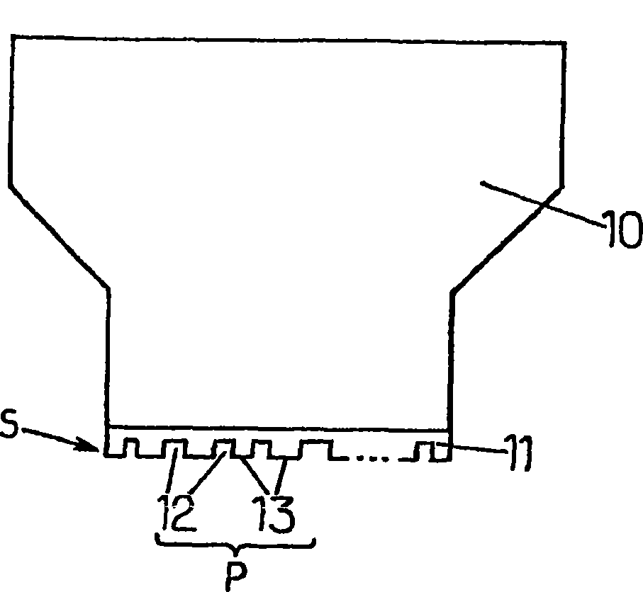
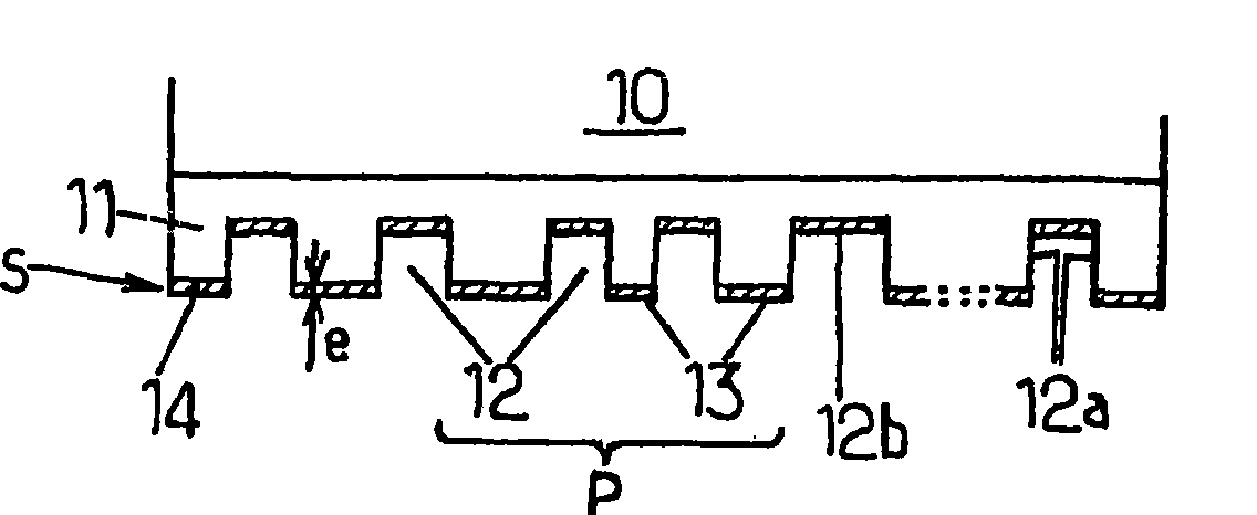
[0107] If the pressure is less than a pressure P limit : The transfer is selective; this is the first embodiment according to the invention: Amplitude hologram.

[0108] If the pressure is greater than a pressure P limit : A complete transfer occurs, accompanied by a permanent impression of the rubber layer, replicating the micro-reliefs complementary to the micro-reliefs composing the stamp pattern P on the stamp.

[0109] The P limit It is determined for a 30nm gold or aluminum layer on rubber deposited under the above conditions.

[0110] P limit is 45g / mm of the surface of the stamp protrusions 13 that make up the pattern P 2 ~60g / mm 2 pressure.

[0111] The table below shows the results under different test conditions:

[0112]

[0113] Pressure applied to selectively transfer gold example:

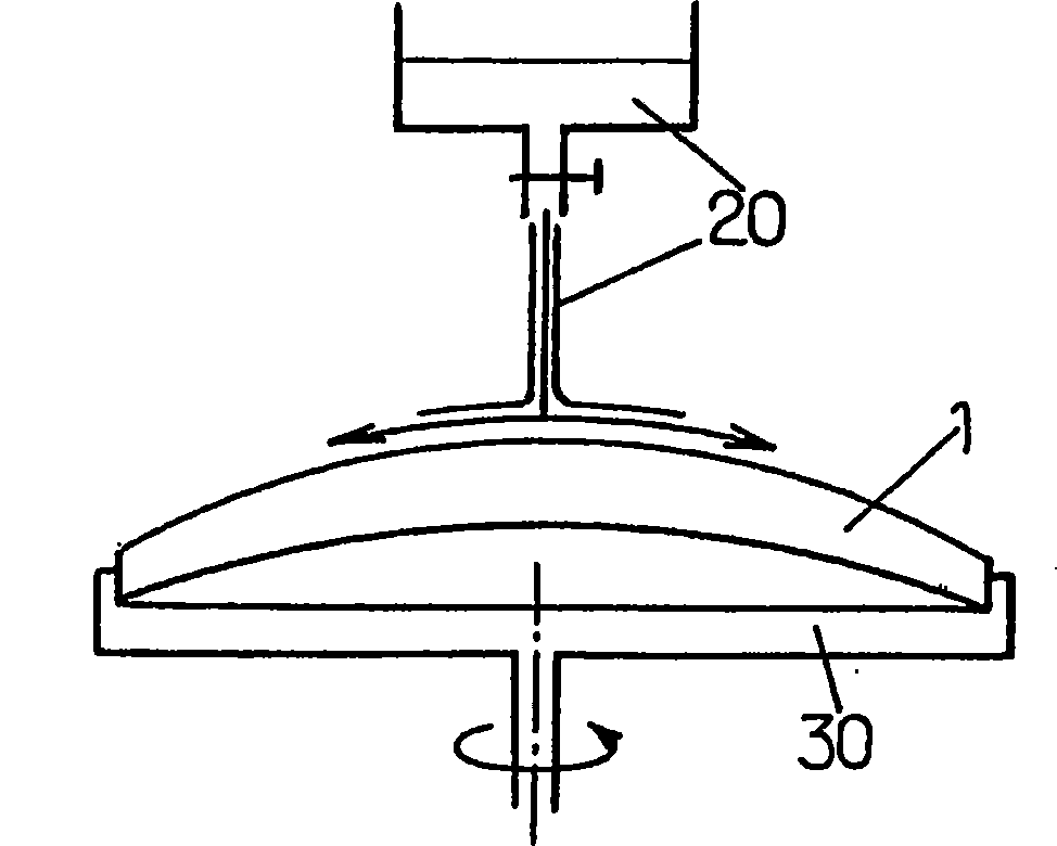
[0114] The stamper is applied to the convex surface of an ophthalmic lens covered with a layer of rubber deposited under the above conditions (the radius of curvature of t...


PUM

PropertyMeasurementUnit
sizeaaaaaaaaaa
sizeaaaaaaaaaa
sizeaaaaaaaaaa

Abstract

The inventive method consists in transferring a pattern (P) onto the optical article (1) in the form of one or several portions of transferable material (3, 4b) retained by a latex layer (2) and in applying one or several transferable material portions with the aid of a pad when the latex layer is formed on the article and the latex is not yet dried. The use of the latex as an adhesive material makes it possible to use the different materials in the form of a transferable material. Said method is particularly suitable for producing patterns in the form of holograms on optical lenses, in particular ophthalmic lenses. Said latex layer can also form a product protection against future potential impacts.

Description

technical field [0001] The invention relates to a method for transferring a micron-scale pattern onto an optical article, and an optical article containing the pattern obtained by the method. The invention is particularly suitable for products of the optical lens type, in particular of the spectacle lens type. This method is very advantageous for introducing a holographic pattern. Background technique [0002] Printing a predetermined pattern onto a finished or in-progress product may be necessary, for example, especially for decorative purposes, to display the product's trade mark or to prevent possible counterfeiting of the product. [0003] To this end, a number of printing methods have been developed, which are often referred to as "soft" lithographic methods to distinguish them from traditional photolithographic methods used to manufacture integrated circuits. While those photolithographic methods are based on selectively irradiating and decomposing resin mask portio...

Claims


Application Information

Patent Timeline
Patent Type & Authority Patents(China)
IPC IPC(8): B41F17/00B41K3/14G02C7/02
CPCG03H2270/55B41F17/001Y10S977/887G03H2210/53B29D11/00336B29D11/00884B29D11/00009G02C7/02B41F17/00B41K3/14G02C7/00
Inventor 克里斯泰勒·德弗朗科
Owner ESSILOR INT CIE GEN DOPTIQUE
Learn More