
Multi-force output air gap monostable permanent magnet control mechanism with manual emergency switching mechanism

A technology of opening mechanism and permanent magnet operation, applied in the direction of contact drive mechanism, contact operating mechanism, electrical components, etc.

Active Publication Date: 2010-07-14
BEIHANG UNIV +1
View PDF4 Cites 0 Cited by
  • Summary
  • Abstract
  • Description
  • Claims
  • Application Information

AI Technical Summary

Problems solved by technology

[0007]In order to solve the defects of the existing permanent magnet operating mechanism, such as large non-working air gap, low magnetic flux utilization rate, and large volume of the operating mechanism

Method used


Image

  • Multi-force output air gap monostable permanent magnet control mechanism with manual emergency switching mechanism
  • Multi-force output air gap monostable permanent magnet control mechanism with manual emergency switching mechanism
  • Multi-force output air gap monostable permanent magnet control mechanism with manual emergency switching mechanism

Examples


Embodiment Construction

[0070] The present invention will be further described in detail below in conjunction with the accompanying drawings.

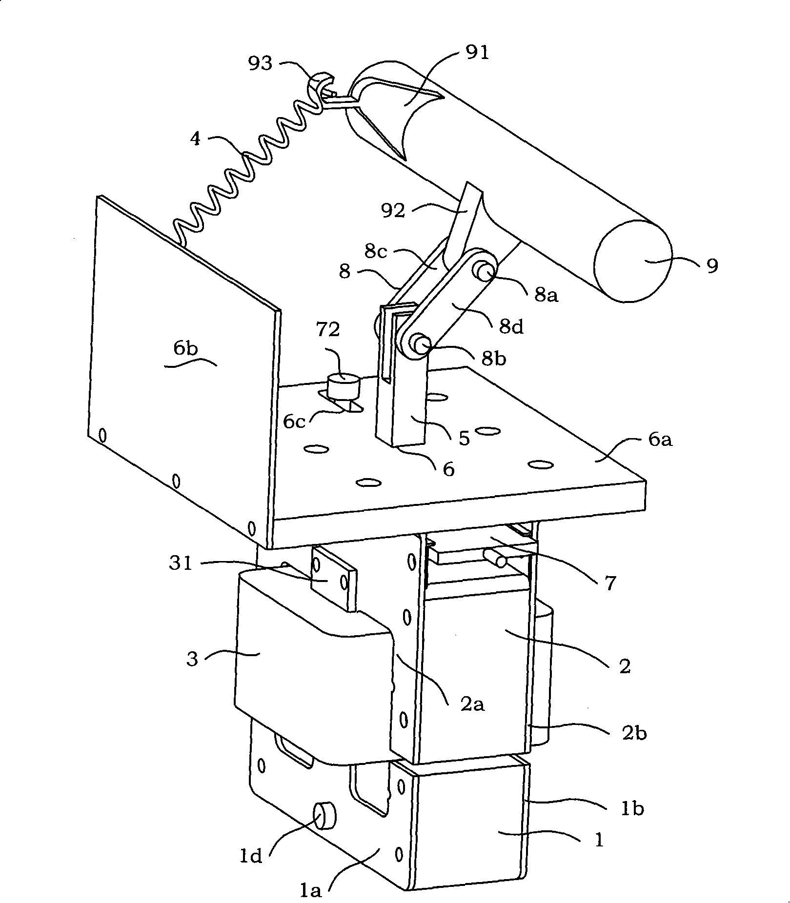
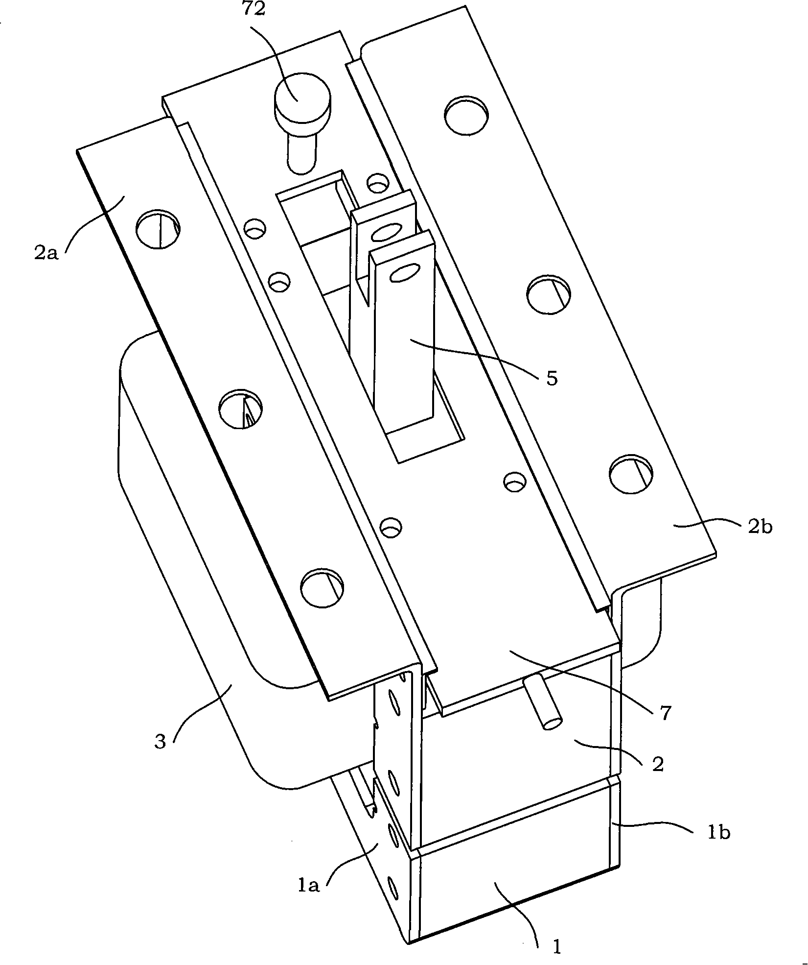
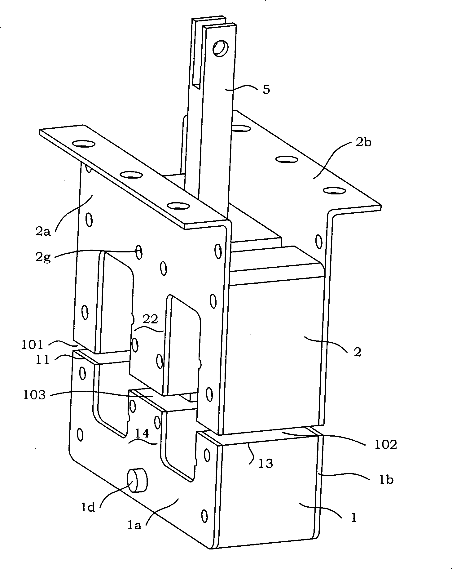
[0071] see figure 1 , Figure 1A , Figure 1B As shown, the present invention is a multi-force air gap monostable permanent magnet operating mechanism with a manual emergency opening mechanism, including a moving iron core 1, a static iron core 2, an opening and closing coil 3, an opening spring 4, Transmission rod 5, support plate 6a, fixed plate 6b, emergency opening mechanism 7, connector 8, rotating shaft 9, A permanent magnet 10, B permanent magnet 11; the moving iron core 1 is placed under the static iron core 2, and the moving iron core 1 and There are three air gaps (A air gap 101, C air gap 103, B air gap 102) between the static iron cores 2; On the A boss 2c of the C pressing piece 2a and the B boss 2e of the D pressing piece 2b; one end of the opening spring 4 is installed on the fixed plate 6b, and the other end of the opening spring 4 is inst...


PUM


Abstract

The invention discloses a multi-output air gap monostabtle permanent magnetic operating mechanism with manual emergency break-brake mechanism; the permanent magnetic operating mechanism comprises a movable core, a fixed core, a break-closing coil, a break-brake spring, a transmission rod, a supporting plate, a fixed plate, an emergency break-brake mechanism, a connecting piece, a rotating shaft, an A permanent magnet and a B Permanent magnet; the A permanent magnet has the same structure with the B Permanent magnet; the movable core is located under the fixed core; and an A clearance, a C clearance and a B clearance are located between the movable core and the fixed core; one side plate of the supporting plate is mounted with the fixed plate; the supporting plate is mounted on the A lug boss of the C tablet, B lug boss of the D tablet; one end of the break-brake spring is mounted on the fixed plate; the other end of the break-brake spring is mounted on the hanger of angle plate of therotating shaft; the emergency break-brake mechanism is mounted between the C tablet and D tablet of the fixed core; one end of the connecting piece is mounted on the transmission rod; the other end of the connecting piece is mounted on the dummy club of the rotating shaft. The operating mechanism of the invention uses little moving elements to achieve relatively high mechanism operating performance; and in the moving process, the mechanical parts have little abrasion, low failure rate, convenient manufacturing technique and are suitable for aviation and ground mesolow electrical switching field and realize the purpose of rapidly breaking brake and saving energy and reducing consumption.

Description

technical field [0001] The invention relates to a permanent magnet operating mechanism, more particularly, a multi-output air gap monostable permanent magnet operating mechanism with a manual emergency opening mechanism. Background technique [0002] Electrical switches (such as circuit breakers, contactors, etc.) generally mainly include arc extinguishing chambers and operating mechanisms. According to different working principles, the operating mechanism can be divided into electromagnetic operating mechanism, permanent magnet operating mechanism and spring operating mechanism. Among them, the permanent magnet operating mechanism includes a bistable permanent magnet operating mechanism and a monostable permanent magnet operating mechanism. [0003] In the patent application number 02145538.4, the application date was December 18, 2002, and the publication number CN1206687C discloses "a kind of permanent magnet operating mechanism". The permanent magnet operating mechanis...

Claims


Application Information

Patent Timeline
Patent Type & Authority Patents(China)
IPC IPC(8): H01H3/38H01H3/54H01H33/38H01H33/666
Inventor 武建文冯英秦晨张路明
Owner BEIHANG UNIV
Learn More