
Side frame for large-scale box

A box, large-scale technology, applied in the direction of large containers, superstructures, containers, etc., can solve the problems of goods and sidewall steps rubbing or even clamping, sidewall structure and goods damage, etc., to improve connection reliability, reduce Shear stress, the effect of increasing the load space

Inactive Publication Date: 2008-12-10
CIMC VEHICLES (GROUP) CO LTD
View PDF0 Cites 3 Cited by
  • Summary
  • Abstract
  • Description
  • Claims
  • Application Information

AI Technical Summary

Problems solved by technology

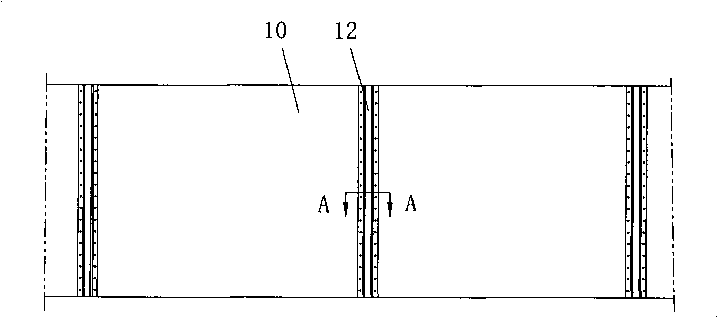
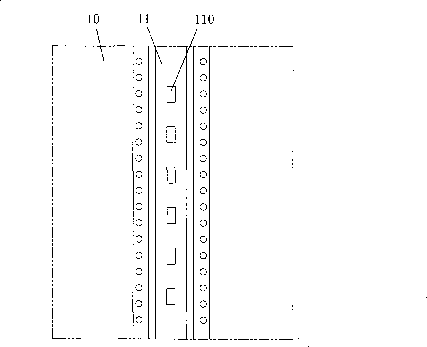
[0005] 1. In order to make the frameless side plate connection structure meet the strength and rigidity requirements of the car body, the cross-section of the inner connector 11 of the side wall of the existing car body adopts a wave-shaped structure in which the middle part protrudes into the car body. In this way, the car body There are protruding steps on the inner surface of the side wall, which makes it easy to rub or even jam between the goods and the steps of the side wall during loading and unloading, which is easy to cause damage to the side wall structure and the goods;

Method used


Image

  • Side frame for large-scale box
  • Side frame for large-scale box
  • Side frame for large-scale box

Examples


Embodiment 1

[0028] The side wall for a large box of the present invention includes a plurality of frameless side panels 20 spliced ​​with each other and a splicing structure connecting the spliced ​​ends of two adjacent frameless side panels 20 . Such as Figure 4 , Figure 5 As shown, the splicing structure includes an inner connecting piece 21 located in the box on both sides of the splicing ends of two adjacent frameless side plates 20, an outer connecting piece 22 located outside the box and connecting the inner connecting piece 21, the outer connecting piece 22 and the The rivet 23 at the splicing end of the frameless side plate 20 . The cross-section of the overlapping part of the inner connector 21 and the splicing end of the frameless side plate 20 is corrugated, and the cross-sectional shape of the contact surface of the overlapping part of the splicing end of the frameless side plate 20 and the inner connector 21 adopts the overlapping part of the inner connector 21 The corrug...

Embodiment 2

[0032] Such as Figure 6 , Figure 7 As shown, this embodiment is basically the same as Embodiment 1, the only difference is that the part of the inner connecting member 31 corresponding to the spaced position adopts a straight shape, and the straight part of the inner connecting member 31 is provided with a through hole 310 . In other embodiments, the straight portion of the inner connecting member 31 may not be provided with the through hole 310 .

Embodiment 3

[0034] Such as Figure 8 As shown, this embodiment is basically the same as Embodiment 1, the only difference is that the outer connecting member 42 adopts a connecting plate.


PUM


Abstract

The invention relates to a side wall used in a large-scale case, comprising a plurality of unframed lateral plates which are mutually spliced and a splice structure for connecting the splice ends of two adjacent unframed lateral plates; the splice structure consists of an inner connecting piece which is clamped at both sides of the splice ends of two adjacent unframed lateral plates and positioned in the case, an outer connecting piece which is positioned at the outside of the case and a rivet used for connecting the inner connecting piece, the outer connecting piece and the splice ends of the unframed lateral plates, and the cross section of the overlap section of the inner connecting piece and the splice end of the unframed lateral plate is corrugated. The side wall used in a large-scale case in the invention adopts a corrugated inner connecting piece to replace the original inner connecting piece with a convex wave shape, thus the strength and rigidity of the connecting structure both meet the requirements of the case, steps projected from the inner side of the side wall can be eliminated, mutual collision and damage between cargoes and the steps at the side wall can be avoided, and the loading space of the case can be enlarged; moreover, as the overlap section of the inner and outer connecting pieces and the splice ends of two adjacent unframed lateral plates adopts inosculated corrugation for matching, the shearing stress of the rivet is reduced and the transverse connecting strength and connecting reliability of the side wall can be improved.

Description

technical field [0001] The present invention relates to a large box structure for loading goods, and more particularly relates to a side wall for a large box. Background technique [0002] Large boxes are widely used in the storage and transportation of goods, such as container boxes, van semi-trailer compartments, van compartments, etc. The side wall structure of large boxes needs to meet the strength requirements for storing and transporting goods, so higher requirements are put forward for the side wall structure. [0003] For example, the side wall of a traditional van-type semi-trailer body is composed of a skeleton structure plus an inner and outer skin (steel plate or aluminum plate) to form a side plate, and the side plates are riveted with each other to form a side wall. This structural feature of the side wall makes it thicker Large, heavy weight, difficult to maintain, and the width of the box is limited, so the side wall of this skeleton structure has gradually ...

Claims


Application Information

Patent Timeline
Patent Type & Authority Applications(China)
IPC IPC(8): B65D90/02B62D33/04
Inventor 姚谷
Owner CIMC VEHICLES (GROUP) CO LTD
Learn More