Alarm monitor for transfusion

A monitor and infusion tube technology, applied in alarms, instruments, hypodermic injection devices, etc., can solve the problems of increased patient pain, patient harm, and easy thrombosis, and achieve the effect of reducing ineffective labor, high energy efficiency, and low cost

Inactive Publication Date: 2008-12-03
朱建彬
View PDF0 Cites 3 Cited by
  • Summary
  • Abstract
  • Description
  • Claims
  • Application Information

AI Technical Summary

Problems solved by technology

[0002] In the process of intravenous infusion, when the liquid in the infusion set is nearly empty, if the infusion is not stopped in time or the infusion bottle is replaced, it will cause blood return and coagulation, which will hinder the continued infusion, add extra pain to the patient, and easily form a thrombus , potentially harmful to patients
Existing infusion sets include bottle stopper piercer, air filter, flow observation barrel, infusion tube, flow regulator, liquid medicine filter, and intravenous infusion needle. They do not have the function of sending out an alarm to remind medical staff, and they always need to be supervised during use. , the nursing workload is heavy and error-prone, and doctor-patient conflicts occur frequently

Method used


Image

  • Alarm monitor for transfusion
  • Alarm monitor for transfusion
  • Alarm monitor for transfusion

Examples


Embodiment 1

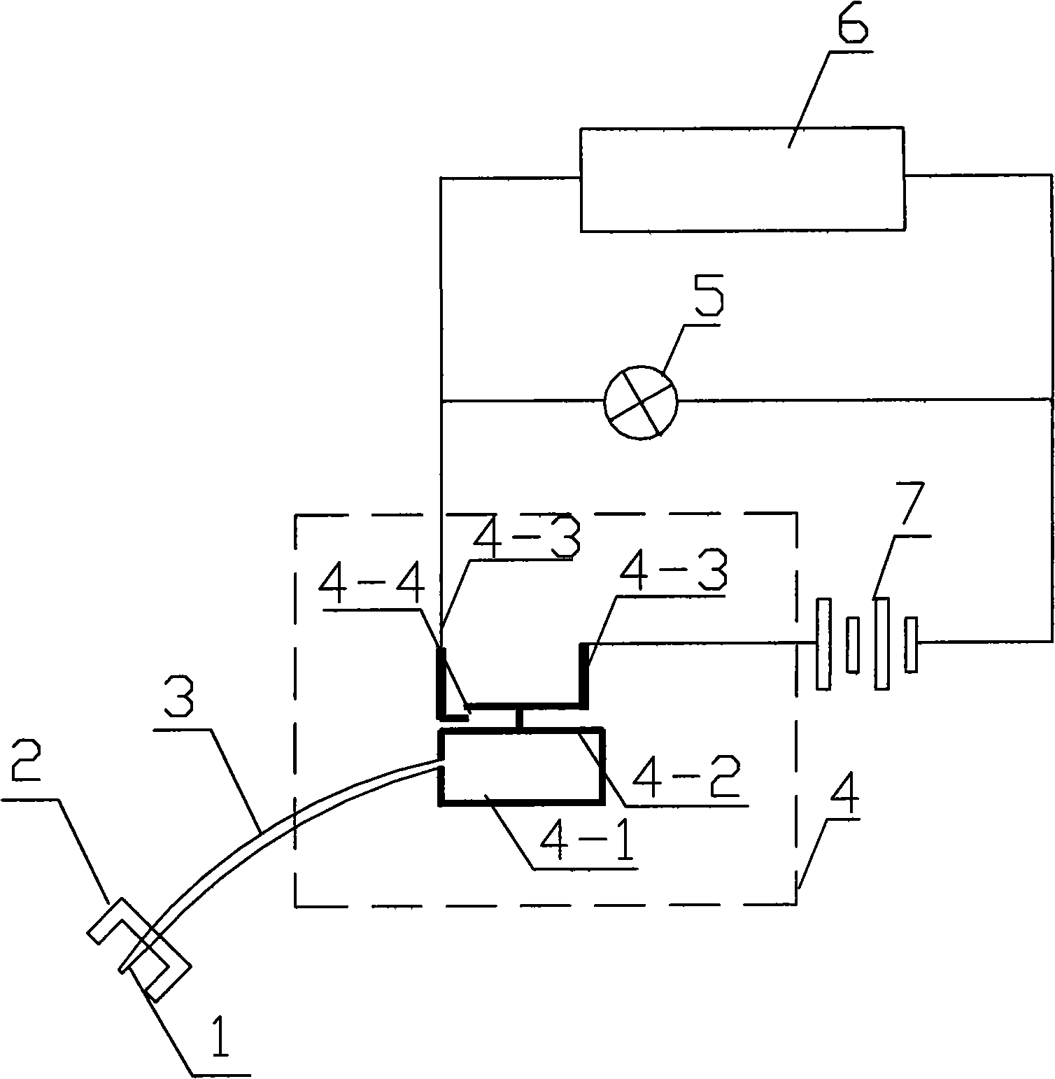
[0029] Embodiment 1: In actual use, when the microswitch electrode 4-3 is designed outside the barometric chamber 4-1, such as figure 2 , image 3 As shown, the pressure-sensitive sheet 4-2 is in the original state during normal infusion, and the circuit is open. The present invention is in the working state of pressure monitoring, and the monitoring process does not consume power. When the infusion is about to be completed, the air pressure in the alarm tee of the infusion set changes, causing the air pressure in the air pressure chamber 4-1 to change accordingly, and the pressure-sensitive sheet 4-2 is sunken downward, driving the micro switch electrode 4- 3. Close, switch on the circuit, start the alarm device, and reach the purpose of prompting the medical staff. The present invention can be used in any occasion where the air pressure change is used to control the alarm device.

Embodiment 2

[0030] Embodiment 2: In actual use, when the microswitch electrode 4-3 is designed inside the barometric chamber 4-1, such as Figure 4 , Figure 5 As shown, the pressure-sensitive sheet 4-2 is in the original state during normal infusion, and the circuit is open. The present invention is in the working state of pressure monitoring, and the monitoring process does not consume power. When the infusion is about to be completed, the air pressure in the alarm tee of the infusion set changes, causing the air pressure in the air pressure chamber 4-1 to change accordingly, and the pressure-sensitive sheet 4-2 is sunken upwards, driving the micro-switch electrode 4-3 at the same time Close, switch on the circuit, start the alarm device, and achieve the purpose of prompting medical staff. The present invention can be used in any occasion where the air pressure change is used to control the alarm device.


PUM


Abstract

The present invention relates to a transfusion alarm monitor, in particular to a monitor which realizes alarming according to the pressure change of a transfusion tube. The monitor comprises an acicular joint 1, a protecting cap 2, an air duct 3, an air pressure microswtich 4, an alarm indication lamp 5, an alarm device 6, and a battery unit 7. One end of the air duct 3 is connected with the acicular joint 1 and is provided with the protecting cap 2. The other end of the air duct 3 is communicated with an air pressure cabin 4-1 of the air pressure microswitch 4. The upper side or the lower side of the air pressure cabin 4-1 is provided with a pressure sensing sheet 4-2. The pressure sensing sheet 4-2 is connected with an electrode 4-3 of the air pressure microswitch 4. The alarm indication lamp 5 and the alarm device 6 are connected in parallel and are controlled in a circuit by the air pressure microswitch 4. The monitor can realize the auto-alarm after the transfusion is finished; according to the pressure change of the transfusion tube, the monitor has the functions of automatically reminding medical care personnel and reducing labor intensity of nursing work.

Description

technical field [0001] The invention relates to a medical alarm, in particular to a monitor which realizes alarm according to the pressure change of the infusion tube. Background technique [0002] In the process of intravenous infusion, when the liquid in the infusion set is nearly empty, if the infusion is not stopped in time or the infusion bottle is replaced, it will cause blood return and coagulation, which will hinder the continued infusion, add extra pain to the patient, and easily form a thrombus , causing potential harm to patients. Existing infusion sets include bottle stopper piercer, air filter, flow observation barrel, infusion tube, flow regulator, liquid medicine filter, and intravenous infusion needle. They do not have the function of sending out an alarm to remind medical staff, and they always need to be supervised during use. , the nursing workload is heavy and error-prone, and doctor-patient conflicts occur frequently. Contents of the invention [000...

Claims


Application Information

Patent Timeline
Patent Type & Authority Applications(China)
IPC IPC(8): A61M5/14A61M5/48G08B21/18H01H35/24
Inventor 朱建彬
Owner 朱建彬
Why Eureka
Try Eureka