Filtrating type vapor-liquid separating device
A vapor-liquid separation and filtration technology, applied in the separation method, charging system, liquid degassing, etc., can solve problems such as inhaled gas, fuel injector safety hazards, good fuel filters, etc., to prolong the service life, Protect the effect of normal work
Inactive Publication Date: 2010-12-01
塞尔福(厦门)工业有限公司
View PDF4 Cites 0 Cited by
- Summary
- Abstract
- Description
- Claims
- Application Information
AI Technical Summary
Problems solved by technology
This kind of vapor-liquid separation device is located under the fuel tank and has a large size, while the air bubble removal device is located in the belly of the fuel tank. The pipeline connecting the two is slender and located outside the fuel tank, which is not good in aesthetics, productivity and reliability. Ideal
At the same time, the height difference of this type of vapor-liquid separation device relative to the fuel injector is small, and a slight air bubble may cause the fuel supply flow and pressure to be too small, causing the fuel injector to inhale gas, and the working stability will be affected.
In addition, due to structural limitations, this type of vapor-liquid separation device cannot be installed with a fuel filter that has a good filtering effect and does not affect the fuel supply system, which poses a great safety hazard to the fuel injector.
Method used
View moreImage
Smart ImageViewing Examples

Examples
Embodiment 1
Embodiment 2
Embodiment 3
Login to View More PUM
 Abstract
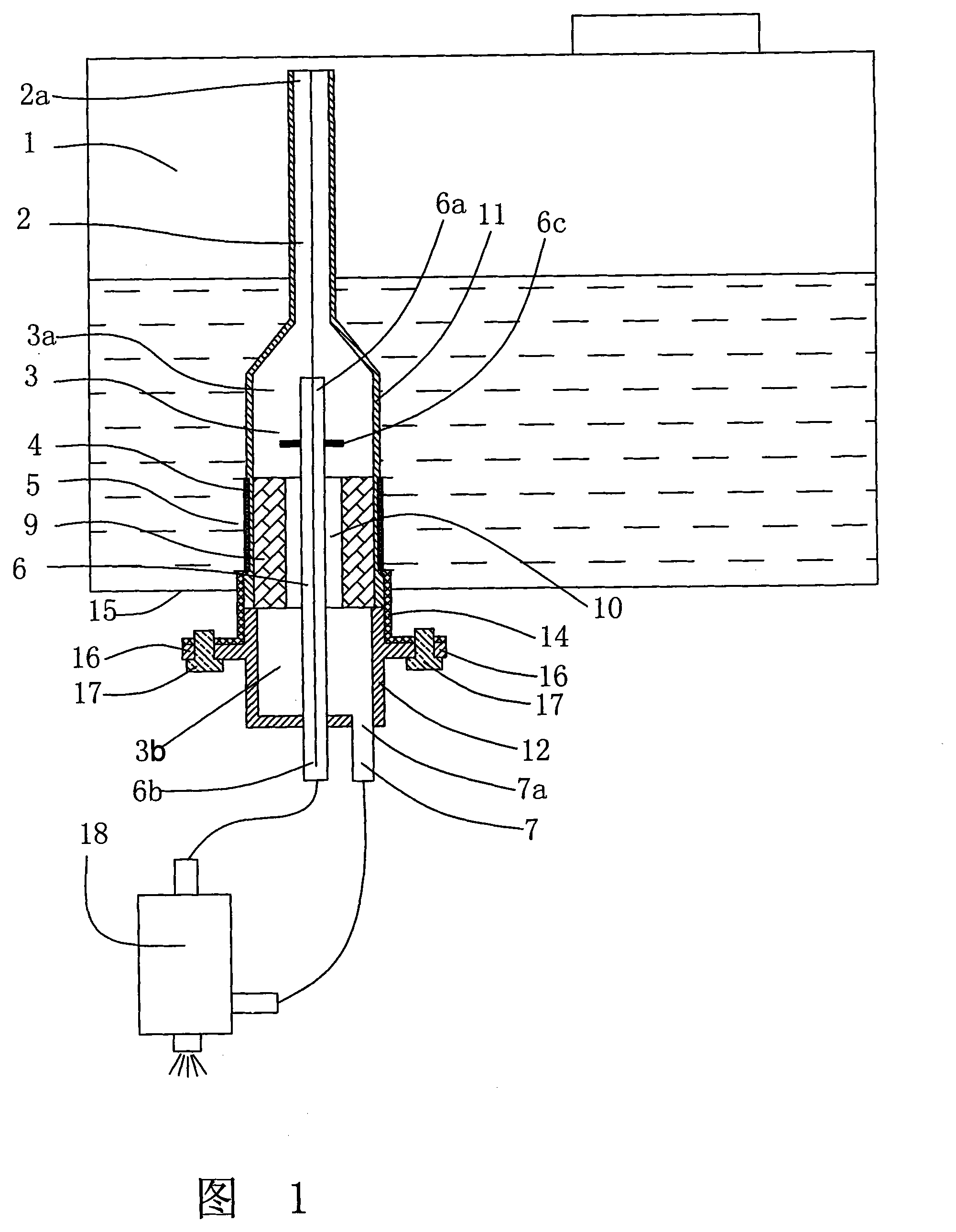
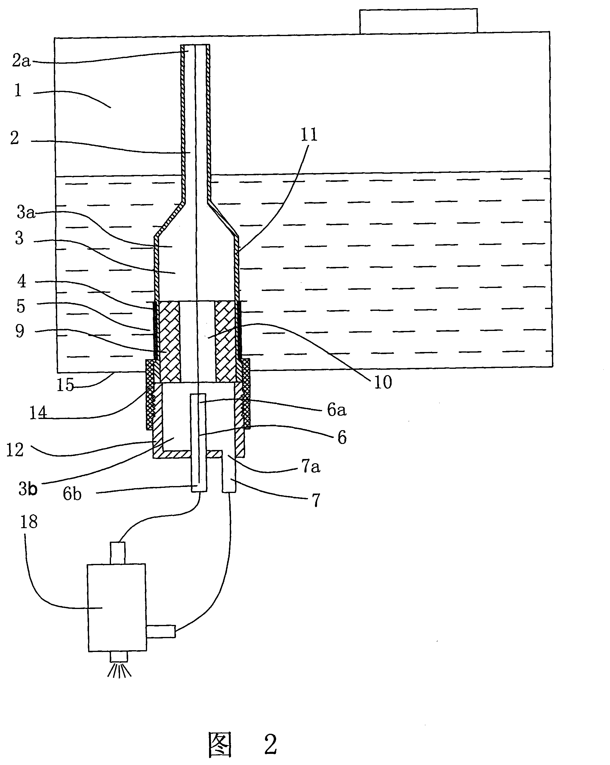
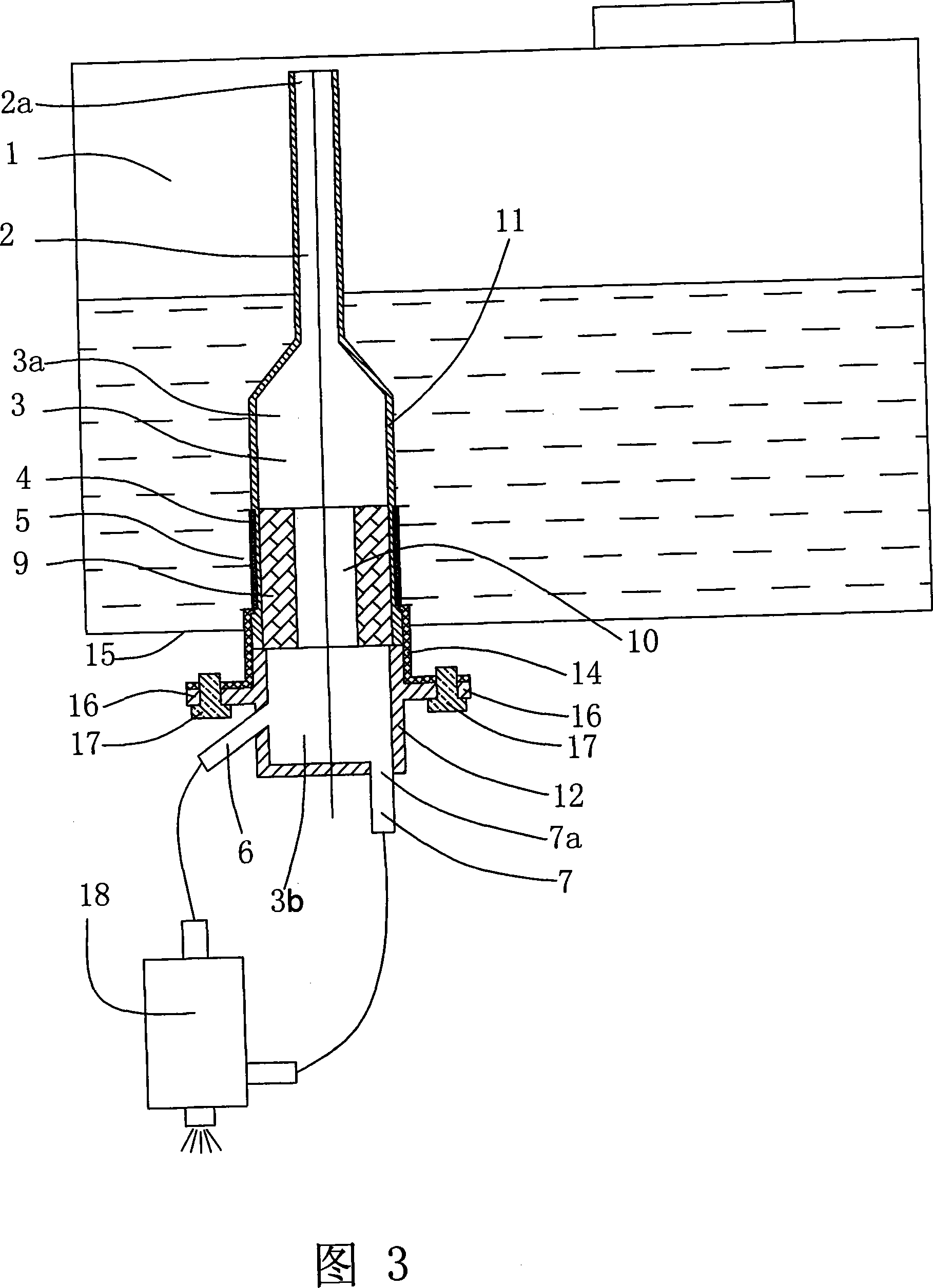
A filtering gas-liquid separation device belongs to the technical field of fuel supply of an engine which includes an exchange cubage and an oil return tube used for receiving the return oil of the fuel sprayer; an exhaust channel is arranged above the exchange cubage; an oil outlet tube used for supplying oil to a fuel sprayer is arranged below the exchange cubage; an oil inlet used for leading the fuel to enter the device from an oil box is arranged in a fuel box; a multiple fuel filters are arranged between the oil inlet and the exchange cubage; the outlet of the oil return tube is arranged in the exchange cubage so as to lead the distance to be larger than the size of the largest confusion area of the liquid of the oil return tube and lead the air bladders of the oil return tube to beincapable of entering the oil outlet tube. The invention can be suitable for a pulse electric fuel spraying system which not only ensures the fuel steams to be exhausted in time, increase the filtering of multiple fuels and lead the fuel spraying system to work reliably, but also can carry out complete protection on the fuel sprayer and obtain further improvements on the productive performance and beautiful performance simultaneously.
Description
A filter type vapor-liquid separation device technical field The invention belongs to the technical field of engine (internal combustion engine) fuel supply, and in particular relates to a vapor-liquid separation device suitable for a pulse type electronic fuel injection device with a low-pressure fuel supply circuit. Background technique In a pulsed electronic fuel injection system that has been widely used (such as Chinese patent ZL01103954.X, and Japanese patent 2003-83192), the fuel is directly obtained from the fuel tank under normal pressure. Since commercial gasoline contains low-boiling components, These components will produce a large number of air bubbles under normal pressure or slightly high temperature. If these air bubbles cannot be discharged in time in the fuel supply system, the electronic fuel injection system will appear in an abnormal working state. In addition, gasoline contains more impurities, and the rust in the fuel tank after long-term use also gr...
Claims
Login to View More Application Information
Patent Timeline
 Patent Type & Authority Patents(China)
IPC IPC(8): F02M37/00F02M37/22B01D19/00
Inventor 郗大光刘晓吉张平杨延相
Owner 塞尔福(厦门)工业有限公司
Features
- R&D
- Intellectual Property
- Life Sciences
- Materials
- Tech Scout
- Unparalleled Data Quality
- Higher Quality Content
- 60% Fewer Hallucinations
Learn More Browse by: Latest US Patents, China's latest patents, Technical Efficacy Thesaurus, Application Domain, Technology Topic, Popular Technical Reports.
© 2025 PatSnap. All rights reserved.Legal|Privacy policy|Modern Slavery Act Transparency Statement|Sitemap|About US| Contact US: help@patsnap.com