Highly strong, non-oriented electrical steel sheet and method for manufacture thereof
A non-directional, electromagnetic steel plate technology, applied in the direction of inorganic material magnetism, circuits, magnetic materials, etc., can solve the problems of inability to ensure strength, magnetic properties and steel plate shape, and achieve excellent magnetic properties, excellent fatigue properties, and high-strength steel plate shape and the effect of the magnetic properties
- Summary
- Abstract
- Description
- Claims
- Application Information
AI Technical Summary
Problems solved by technology
Method used
Image
Examples
Embodiment 1
[0154] (Embodiment 1: Inventions (1), (2))
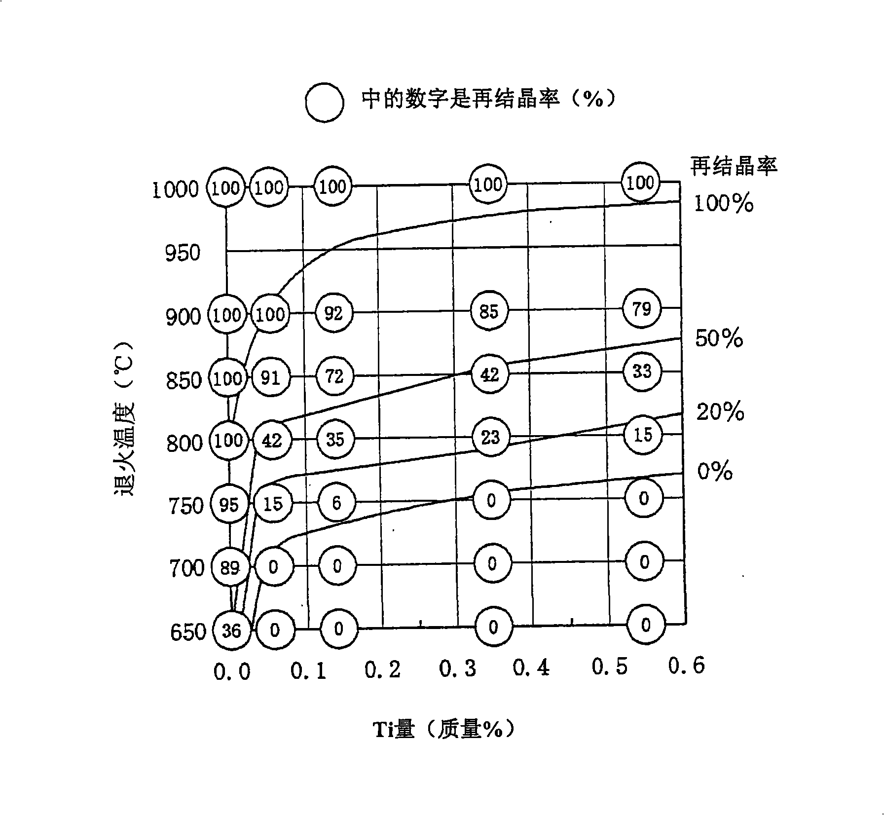
[0155] The steel slabs with the composition shown in Table 1 were hot-rolled to a thickness of 2.5 mm, annealed at 900° C. for 60 s, and then pickled and cold-rolled to a thickness of 0.35 mm.
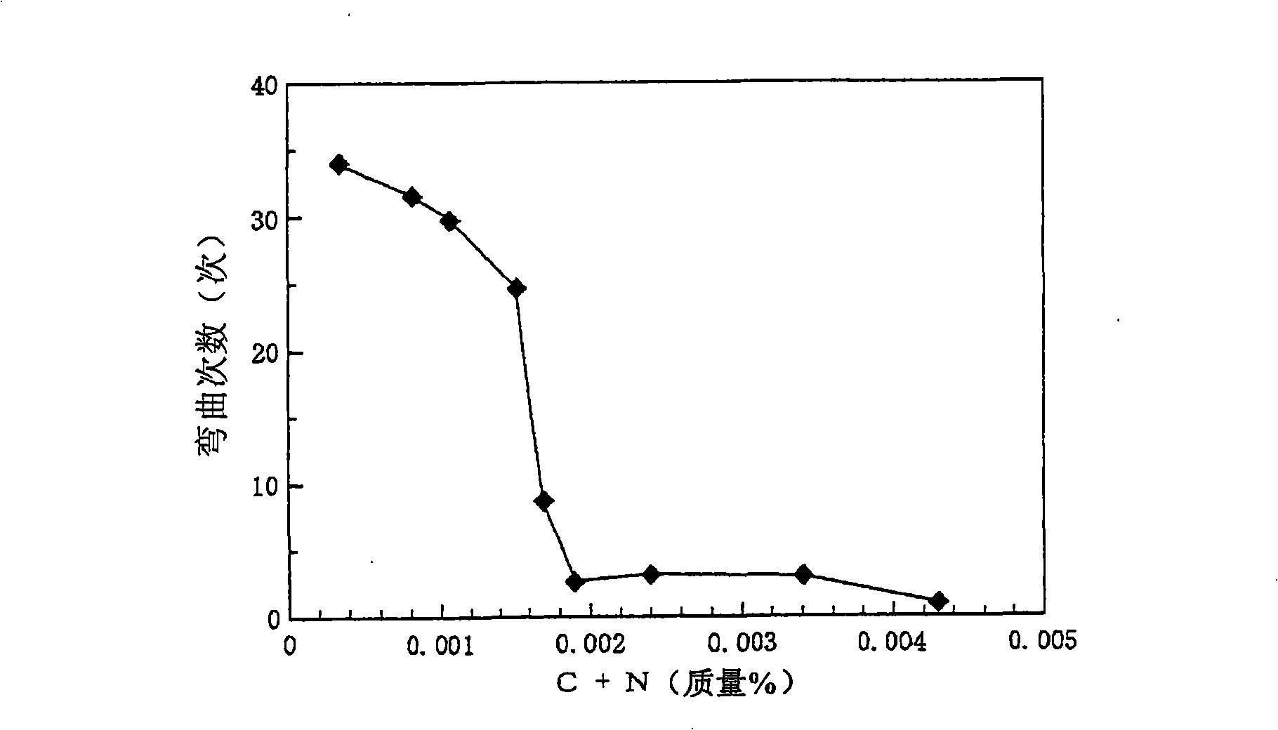
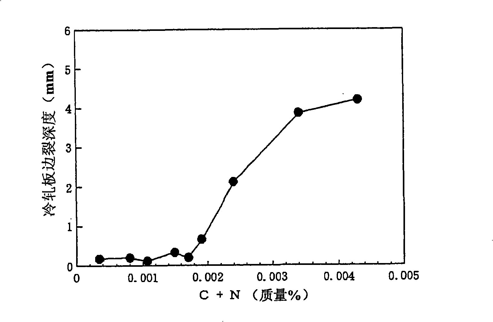
[0156] Here, steel G having a Ti content exceeding the range of the present invention was not subjected to subsequent treatments because scale-like folding defects often occurred after cold rolling. In addition, steel N containing almost no Ti as high as 4.3% of Si, and steel P containing Si exceeding the range of the present invention, were not subjected to subsequent treatment because the steel sheet was broken during cold rolling. Next, final annealing for a soaking time of 20 s was implemented under the conditions shown in Table 2. In addition, the tension in the furnace was measured with a tension gauge in the furnace of a tension roll type in which a load cell was incorporated in the lower part of the bearing.
[0157] Table 1
[01...
Embodiment 2
[0170] (Embodiment 2: Inventions (1), (2))
[0171] After hot-rolling the slabs of steels A and D in Table 1 to a thickness of 2.5 mm, the hot-rolled slabs were annealed at 800°C for 60 s, pickled and cold-rolled to a thickness of 0.35 mm to form coils. material. The obtained coil was subjected to final annealing in a continuous annealing furnace under the conditions shown in Table 3, and the same evaluation as in Example 1 was performed.
[0172] The results are shown in Table 3 together. It can be seen from Table 3 that steel A and D have a small improvement in the shape of the steel plate even if the tension in the furnace is high at the lower annealing temperature of 650 °C. On the other hand, when the annealing temperature was increased to 800°C and the tension in the furnace was controlled within the range of the present invention, the shape of the coil was significantly improved. By this final annealing, the conventional steel A has a large strength drop, which is no...
Embodiment 3
[0176] (Embodiment 3: Inventions (1), (2))
[0177] The steel slabs with the composition shown in Table 4 were cold-rolled to the final thickness under any one of the following conditions a to c.
[0178] a: After hot-rolling to a plate thickness of 2.0 mm, the hot-rolled plate is not annealed, and warm-rolled to a final plate thickness of 0.35 mm (steel plate temperature is 250° C.).
[0179] b: After hot-rolling to a plate thickness of 3.8 mm, no hot-rolled plate annealing is performed, cold-rolled to 1.5 mm, and then intermediate annealing at 1000° C. for 30 seconds, and then cold-rolled to a final plate thickness of 0.35 mm.
[0180] c: After hot rolling to a plate thickness of 2.5mm, after annealing of the hot rolled plate at 1050°C-holding for 30s, cold rolling to 1.0mm, and then implementing intermediate annealing at 1000°C-holding for 30s, and warm rolling to the final plate thickness of 0.20mm (Steel plate temperature is 200°C).
[0181] Next, final annealing with a...
PUM
| Property | Measurement | Unit |
|---|---|---|
| Bending radius | aaaaa | aaaaa |
| Bending angle | aaaaa | aaaaa |
Abstract
Description
Claims
Application Information
 - R&D Engineer
- R&D Manager
- IP Professional
- Industry Leading Data Capabilities
- Powerful AI technology
- Patent DNA Extraction
Browse by: Latest US Patents, China's latest patents, Technical Efficacy Thesaurus, Application Domain, Technology Topic, Popular Technical Reports.
© 2024 PatSnap. All rights reserved.Legal|Privacy policy|Modern Slavery Act Transparency Statement|Sitemap|About US| Contact US: help@patsnap.com


