
Method and device for simulating boundary current influencing seepage flow

A technology of water flow and seepage, applied in the direction of measuring devices, instruments, scientific instruments, etc., can solve problems affecting seepage of bank slopes, and achieve the effect of easy implementation, simple operation, and simple principle

Inactive Publication Date: 2012-07-04
TONGJI UNIV
View PDF0 Cites 0 Cited by
  • Summary
  • Abstract
  • Description
  • Claims
  • Application Information

AI Technical Summary

Problems solved by technology

Whether the velocity of the water flow affects the seepage of the bank slope has not been reported so far

Method used


Image

  • Method and device for simulating boundary current influencing seepage flow
  • Method and device for simulating boundary current influencing seepage flow
  • Method and device for simulating boundary current influencing seepage flow

Examples


example

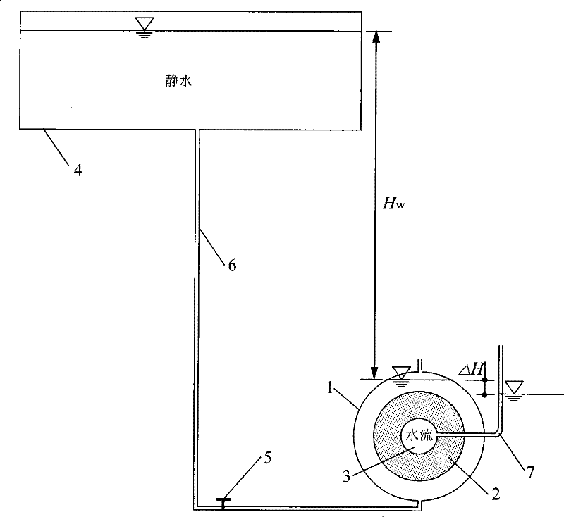
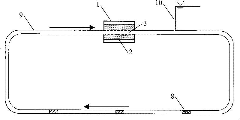
[0021] Example: The inner diameter of the two-flow action chamber is 30cm, and the inner cavity length is 30cm. The water head difference H provided by the water supply tank w = 150cm. The ring column sample adopts uniform sand with a particle size range of 0.2-0.3mm, the average particle size is 0.25mm, and the sample length is 30cm, the outer diameter is 20cm, and the inner diameter is 4.7cm. The diameter of the water circulation pipe is the same as the diameter of the intermediate flow pipe in the ring column sample. During the test, the water temperature of the water supply pool was monitored all the time, it was about 27°C, and the change of water temperature was within 1°C. Through the flow-seepage coupling test of different tangential boundary flow conditions and different combinations of seepage head differences, the test results show that the tangential boundary flow has a significant influence on seepage, and it changes regularly.


PUM


Abstract

Disclosed is a method for simulating the influence on seepage by boundary water flow and a seepage apparatus thereof, which apply the axial symmetry characteristic of ring pillar soil sample seepage, combine the pipe flow theory and adopt a pipe flow mode to provide boundary water flow conditions for soil mass seepage on the basis of the traditional seepage theory, and can reappear the action of the boundary water flow process on seepage and reveal the action law and mechanism. Different pipe flow rates represent different boundary water flow conditions according to the flow rate distributionlaw and flow state change characteristic of pipe flow. The seepage size and boundary water flow conditions are all continuous and adjustable, and the influence on seepage by the boundary water flow can be researched quantitatively. The method and device have advantages of simple implementation and convenient operation.

Description

technical field [0001] The invention relates to a soil mechanical seepage test method, in particular to an experimental device for simulating the effect of boundary water flow on seepage, and belongs to the field of hydraulic engineering. Background technique [0002] As early as 1856, French engineer Darcy (Darcy) proposed Darcy's law of linear seepage. In 1889, Zhukovsky in Russia first derived the differential equation of seepage. In 1922, Pavlovsky proposed the electrical simulation method to solve the seepage field. Since the differential equation of seepage is difficult to obtain its analytical solution under complex boundary conditions, people try to solve it with numerical algorithms. In 1910, L.F.Richardson first proposed the finite difference method. After the 1960s, due to the rapid development of computer and computing technology, people widely used finite element method, boundary element method and many other calculation methods to calculate and solve seepage...

Claims


Application Information

Patent Timeline
Patent Type & Authority Patents(China)
IPC IPC(8): G01N33/00
Inventor 谢立全
Owner TONGJI UNIV
Learn More