Hanging pendulum type beam balancing energy-saving oil pumping machine
A pumping unit and balancing technology, which is applied to mechanical equipment, production fluids, wellbore/well components, etc., can solve the problem that the four-bar linkage mechanism is prone to multiple faults, the adjustment of stroke and stroke is inconvenient, and the operation is reliable. It can achieve the effect of remarkable energy saving effect, simple structure and low manufacturing cost.
- Summary
- Abstract
- Description
- Claims
- Application Information
AI Technical Summary
Problems solved by technology
Method used
Image
Examples
Embodiment 1
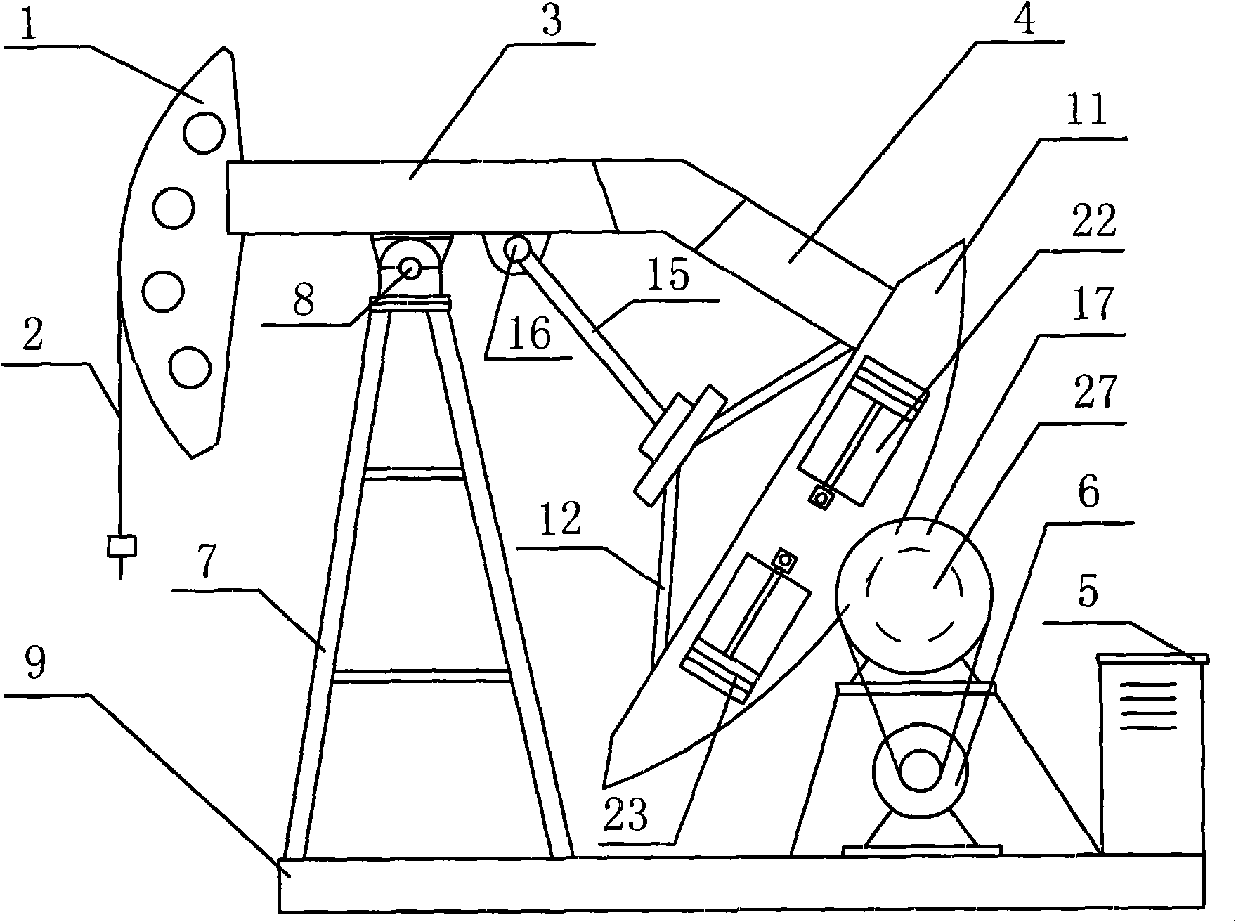
[0039] Embodiment one: as attached figure 1 As shown, when the swing arm assembly 13 is stacked with the tail beam 4 that is tilted downward, the arc segment-shaped suspension weight body 11 can completely replace the counterweight body 10 in the tail beam balance weight device. The motor 6 with forward and reverse functions can use the single-arm structure when the lifting body 11 is reciprocatingly driven according to the operating parameters set in advance by the intelligent control box 5, and the single-arm structure can greatly save The manufacturing cost of the equipment has solved the difficult problem that the conventional pumping unit will run into the scissor difference unavoidably when using double crank operation on both sides of the frame 7.
Embodiment 2
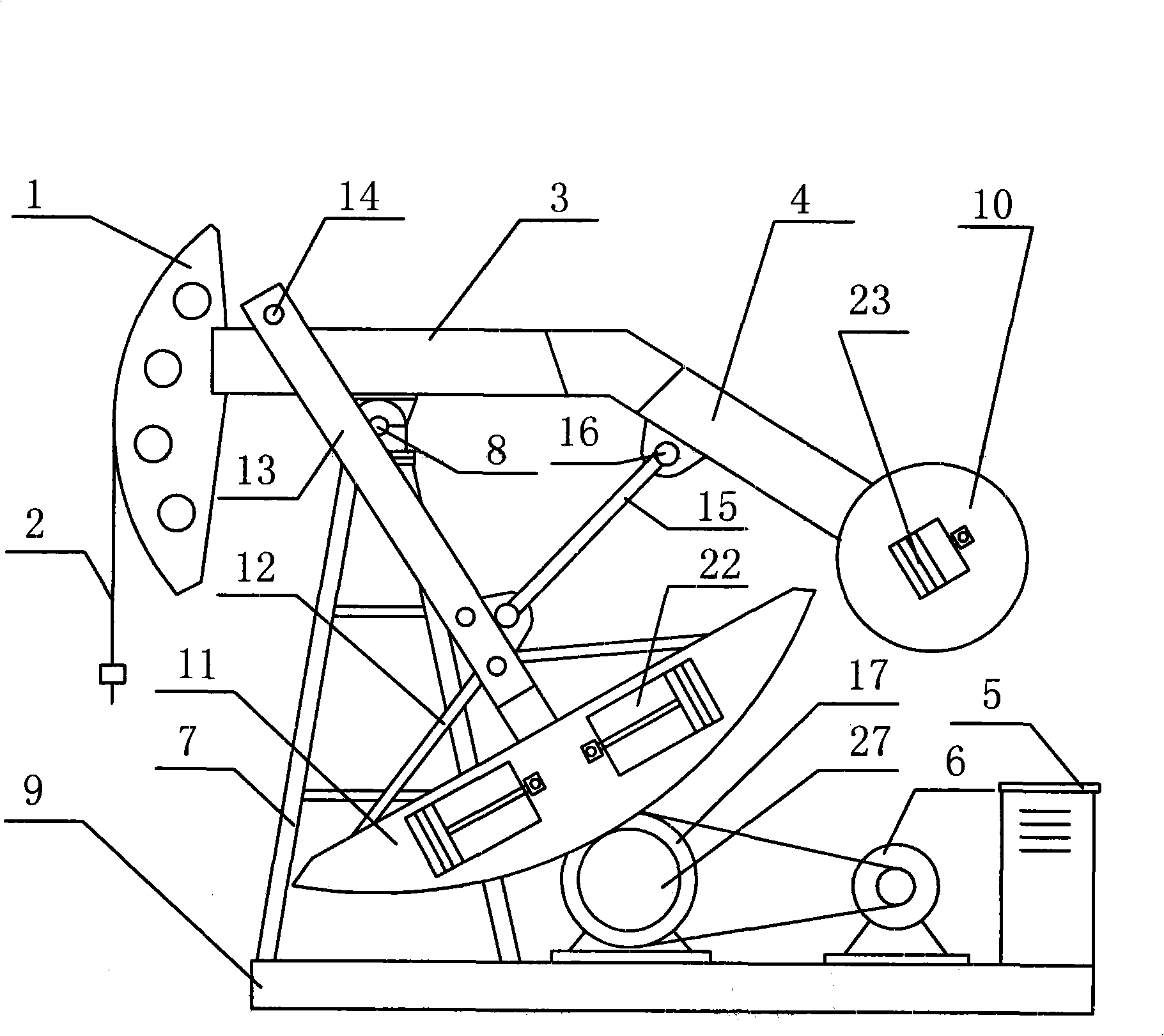
[0040] Embodiment two: as attached figure 2 As shown, the tail beam balance weight device of the equipment is tilted downward, and the suspension pendulum device is symmetrically arranged on the left and right sides of the frame 7 through the connecting piece. 4 are connected, and the lower end of the swing arm assembly 13 and the swing arm link assembly 15 are connected to each other, thereby forming a stable triangular beam structure together with the beam 3 and the tail beam 4, and the arc-shaped suspension connected to the swing arm mechanism Heavy body 11 is driven by the motor 6 with forward and reverse functions to drive the beam to swing back and forth.
Embodiment 3
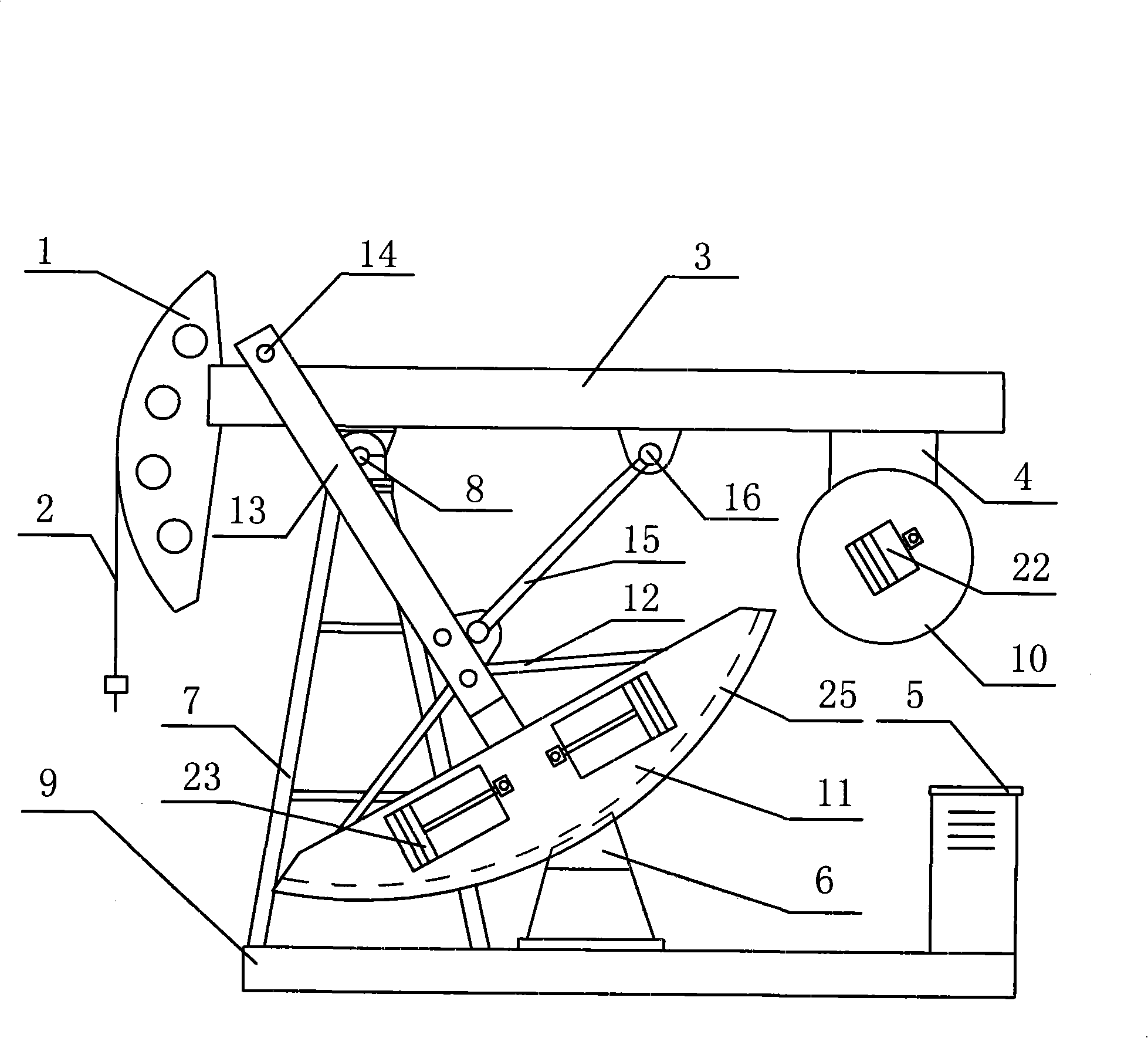
[0041] Embodiment three: as attached figure 2 and image 3 As shown, there are two points of difference with Embodiment 2: one is that the motor used for driving is different, and what Embodiment 2 adopts is a rotating motor, and when it drives the arc-shaped hoisting body 11, it must use wheel surface friction or engagement The transmission mode, and what embodiment 3 adopts is linear motor, when driving hoisting weight 11, what used is the magnetic field effect. The second is that the shape of the tail beam balance weight device on the lower side of the equipment is different. The second embodiment adopts the lower folding beam structure, while the third embodiment adopts the lower hanging beam structure.
PUM
 Abstract
Description
Claims
Application Information
 - R&D Engineer
- R&D Manager
- IP Professional
- Industry Leading Data Capabilities
- Powerful AI technology
- Patent DNA Extraction
Browse by: Latest US Patents, China's latest patents, Technical Efficacy Thesaurus, Application Domain, Technology Topic, Popular Technical Reports.
© 2024 PatSnap. All rights reserved.Legal|Privacy policy|Modern Slavery Act Transparency Statement|Sitemap|About US| Contact US: help@patsnap.com


