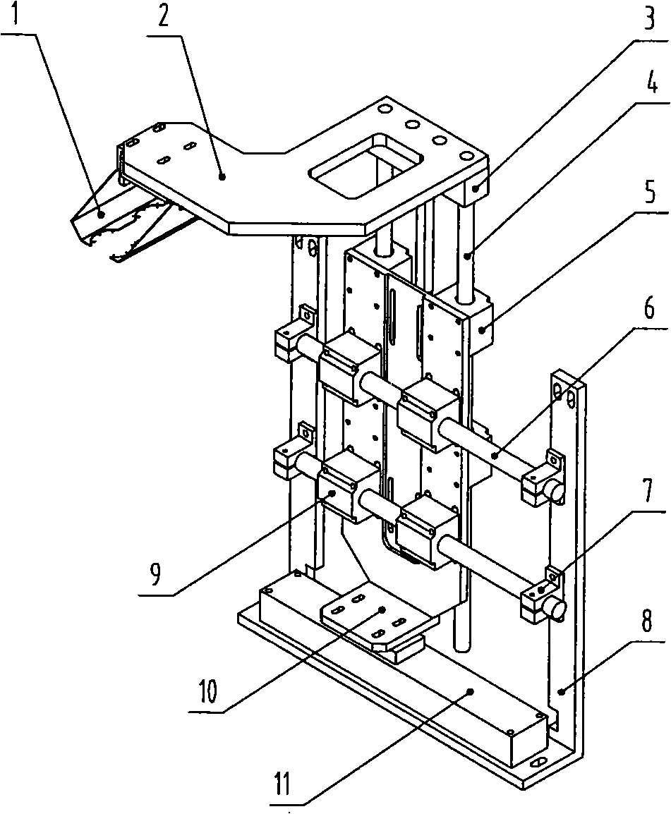
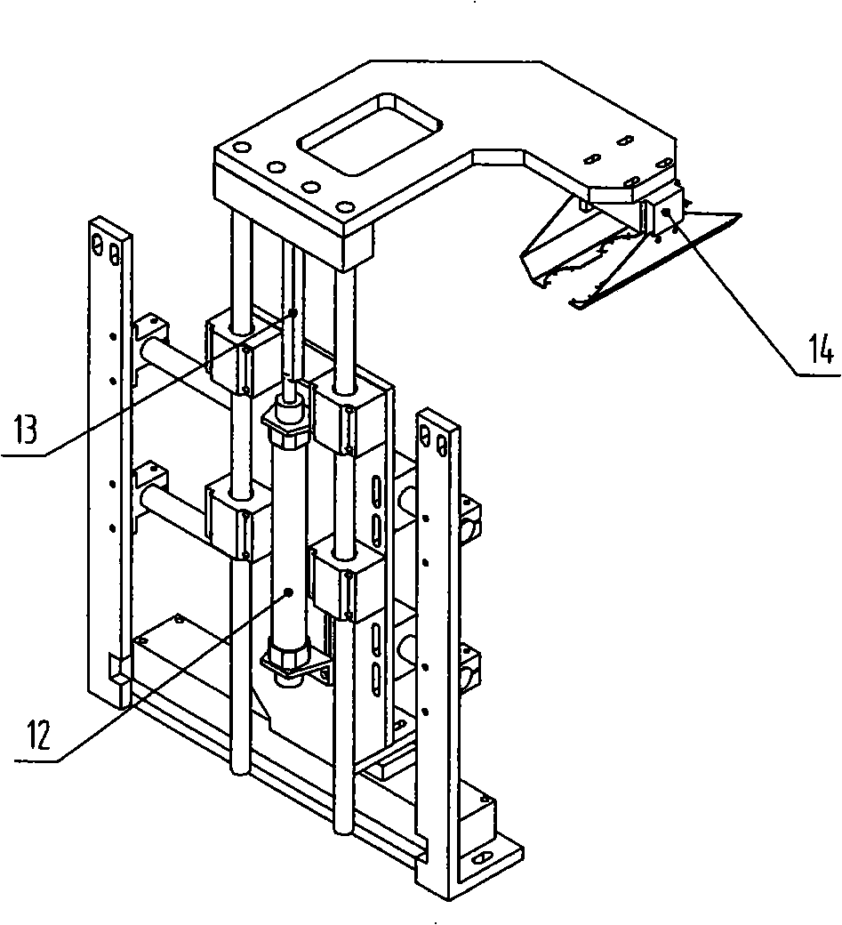
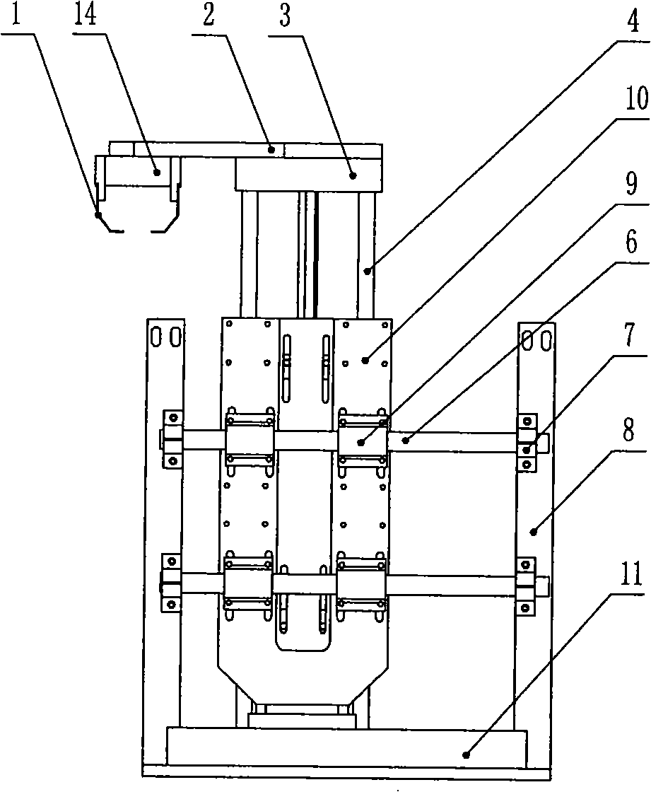
Cake taking device
A cake and parallel block technology, applied in baking, food science, application and other directions, can solve the problems of low production efficiency and high work intensity of operators, and achieve the effects of high production efficiency, simple structure and low manufacturing cost
Inactive Publication Date: 2008-11-19
WUXI YAZHONG PNEUMATIC HYDRAULIC
View PDF0 Cites 9 Cited by
- Summary
- Abstract
- Description
- Claims
- Application Information
AI Technical Summary
Problems solved by technology
This kind of manual cake taking requires the participation of staff, and the work intensity of the operators is high and the production efficiency is low.
Method used
View moreImage
Smart ImageViewing Examples
Examples
Embodiment Construction
Login to View More PUM
 Abstract
The invention relates to a cake pick-up device. The cake pick-up device is characterized in that the device is correspondingly fixed on a pneumatic claw of a cylinder of a large-opening mechanical clamp via two clamping plates; a top plate is connected with two vertical guide rods and a lengthened joint via a top block; the two vertical guide rods respectively penetrates through a first parallel block device and is fixed on one side of a shift plate; a micro-cylinder is fixed on the shift plate via a cylinder support; the piston rod of the micro-cylinder is connected with the lengthened joint; the other side of the shift plate is connected with a second parallel block device which penetrates through a transverse guide rod; the two ends of the transverse guide rod are respectively clamped with the support bases and fixedly connected with the supports via the support bases; and the lower end plate of the shift plate is connected with a rod-free pneumatic rod which is fixed on a support base plate. The device has the advantages that the structure is simple, compact and reasonable; cakes can be picked up conveniently and automatically, and then sent to a specified transfer line or position; the production efficiency is high; the device can follow up with the whole production pace without wasting any time; and the manufacturing cost is low.
Description
Take the cake device technical field The invention relates to a cake fetching device, in particular to a device capable of automatically grabbing cupcakes, and belongs to the technical field of automation devices in bakery food machinery. Background technique At present, during the production process of most cakes, the baking mold filled with cake batter is put into the oven for baking, and the baking mold is taken out after completion. The staff usually use special tongs to separate the cake from the baking mold by hand. Cool before packing. Such manual taking of cakes requires the participation of staff, and the work intensity of the operators is high and the production efficiency is low. Contents of the invention The object of the present invention is to overcome the above disadvantages, thereby providing a cake taking device, which can not only automatically pick the cake from the baking mold, but also conveniently and neatly put the cake on the conveying line, and...
Claims
Login to View More Application Information
Patent Timeline
 IPC IPC(8): A21B3/18
Inventor 葛银松蒋晓东
Owner WUXI YAZHONG PNEUMATIC HYDRAULIC
Features
- R&D
- Intellectual Property
- Life Sciences
- Materials
- Tech Scout
- Unparalleled Data Quality
- Higher Quality Content
- 60% Fewer Hallucinations
Learn More Browse by: Latest US Patents, China's latest patents, Technical Efficacy Thesaurus, Application Domain, Technology Topic, Popular Technical Reports.
© 2025 PatSnap. All rights reserved.Legal|Privacy policy|Modern Slavery Act Transparency Statement|Sitemap|About US| Contact US: help@patsnap.com


