
Intelligent air discharge system for hydraulic system pump front low-pressure end

A hydraulic system and exhaust system technology, which is applied to fluid pressure actuation system components, fluid pressure actuation devices, mechanical equipment, etc., can solve problems such as equipment failures, reduce accident rates, improve work safety, and improve labor efficiency. Effects on productivity and production safety

Active Publication Date: 2008-11-12
STATE GRID ZHEJIANG ELECTRIC POWER CO LTD HANGZHOU POWER SUPPLY CO +1
View PDF0 Cites 8 Cited by
  • Summary
  • Abstract
  • Description
  • Claims
  • Application Information

AI Technical Summary

Problems solved by technology

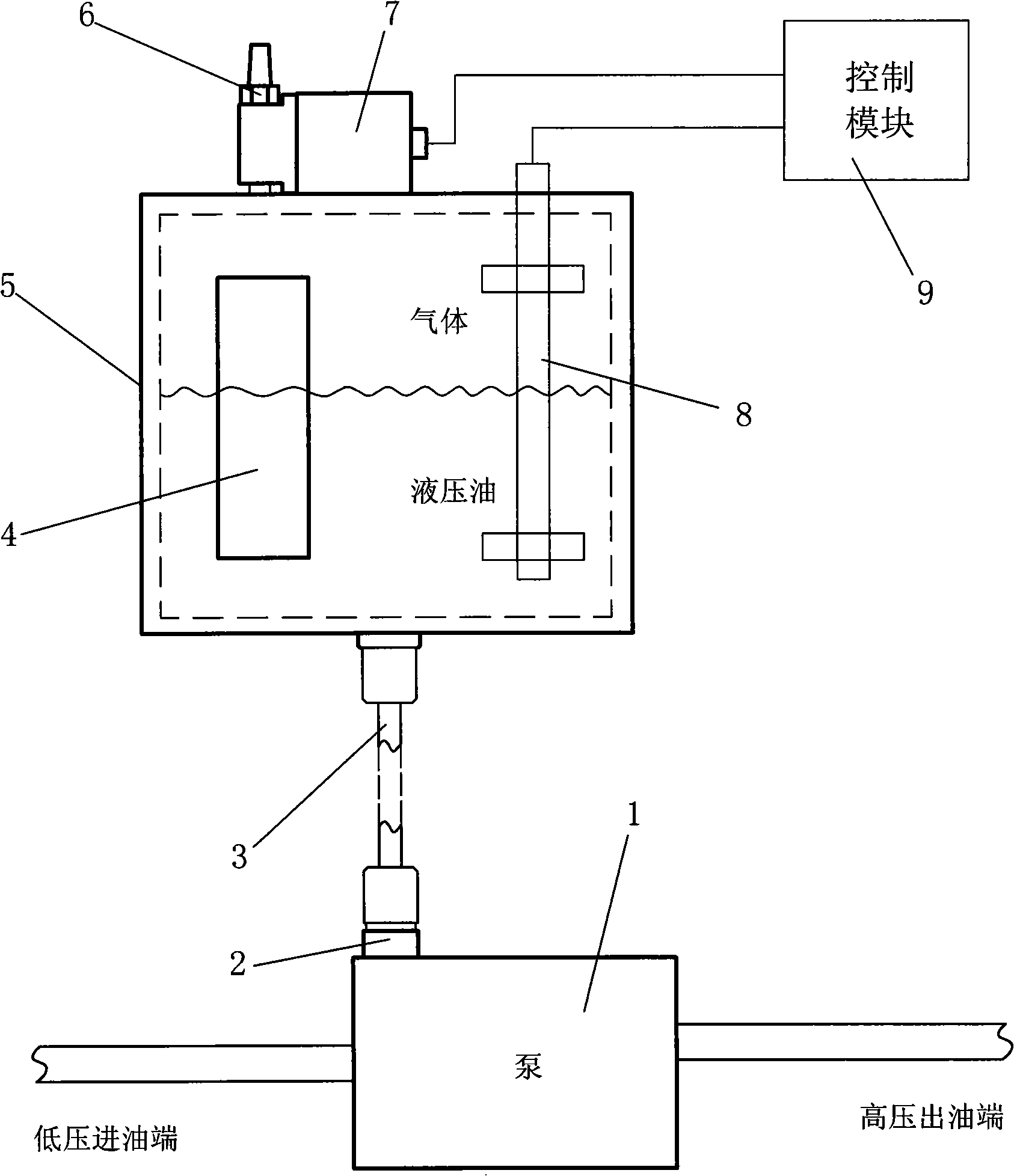
[0013] In order to effectively, thoroughly and conveniently solve the problem of equipment failure caused by gas generated at the low-pressure end in front of the pump in the hydraulic system and ensure the normal operation of the hydraulic system, the purpose of this invention is to provide an intelligent exhaust system for the low-pressure end of the pump in the hydraulic system. The air device is set at a position higher than the pump and lower than the liquid storage tank, and is connected to the low-pressure end of the pump. Using the principle that gas is lighter than liquid, the gas is introduced into the exhaust device, and the air in the low-pressure circuit can be collected concentratedly and discharged. Automatic exhausting according to the situation, avoiding manual and regular blind manual exhausting, greatly reducing the number of times the staff contact high-risk equipment and high-risk environments, can greatly reduce the accident rate of major accidents, and improve the safety and reliability of the equipment. , and improve the labor productivity and production safety of operators

Method used

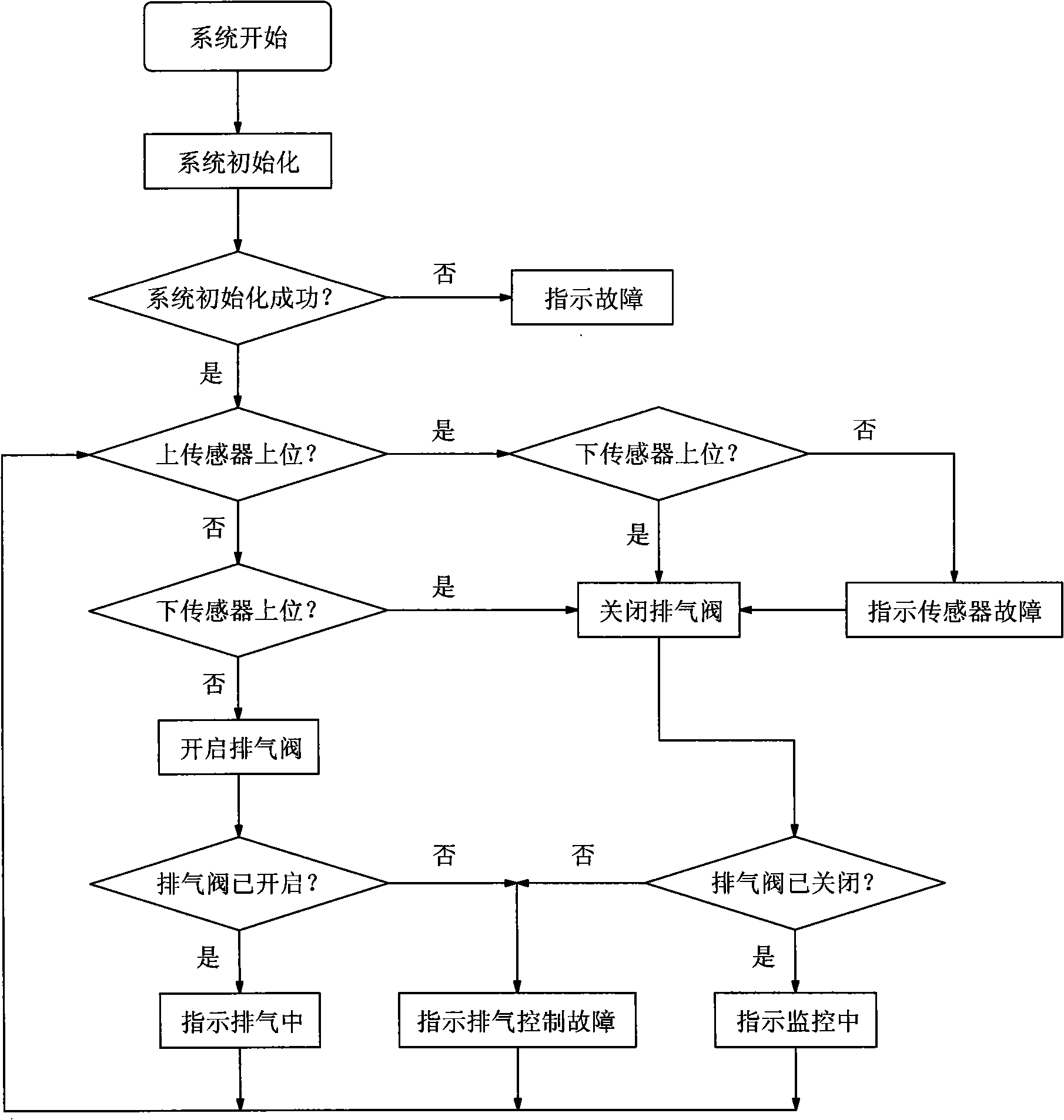

Image

  • Intelligent air discharge system for hydraulic system pump front low-pressure end
  • Intelligent air discharge system for hydraulic system pump front low-pressure end
  • Intelligent air discharge system for hydraulic system pump front low-pressure end

Examples


Embodiment 1

[0035] Such as figure 1 The shown is an intelligent exhaust system for the low-pressure end of the pump in the hydraulic system, including a pump 1. The low-pressure end of the pump 1 is provided with a manual exhaust port 2, and also includes a pump that is higher than the pump 1 and lower than the liquid storage tank. position of the gas storage container 5, the gas storage container 5 is connected with the manual exhaust port 2, the gas storage container 5 is provided with an exhaust port 6, and the exhaust port 6 is connected with an exhaust valve 7, and the gas storage container The container 5 is provided with a high and low liquid level sensor 8, such as image 3 As shown, the above-mentioned exhaust valve 7 and the high-low liquid level sensor 8 are connected to the control module 9, and the above-mentioned control module 9 is connected to a monitoring indicating module and a fault indicating module.

[0036] This embodiment takes the use of this system in a high-volt...


PUM


Abstract

The invention discloses an intelligent exhaust system used for a low-pressure end in front of a pump in a hydraulic pressure system, which comprises the pump and an air vessel, wherein, a manual air outlet is arranged at the low-pressure end in front of the pump, and the air vessel is arranged at the postion higher than the pump and lower than a liquid storage tank. The air vessel is connected with the manual air outlet and provided with an air outlet while the air outlet is connected with an exhaust valve. The air vessel is internally provided with a high and low liquid level sensor, and the exhaust valve and the high and low liquid level sensor are connected with a control module while the control module is connected with a monitoring indication module and a failure indication module. The technical proposal of the invention utilizes the principle that air specific weight is smaller than liquid specific weight to intensively collect the air in a low-pressure loop in front of the pump into the air vessel and automatically exhaust according to the condition of air reserve, thus avoiding the blind and regular manual exhaust, greatly reducing the contact frequency of workers with high risk equipment and high risk environments and greatly reducing the rate of serious accident.

Description

technical field [0001] The invention belongs to the technical field of hydraulic pressure, in particular to an intelligent exhaust system used for exhausting the low-pressure circuit before the pump. Background technique [0002] In the hydraulic system, the hydraulic medium in the low-pressure fluid storage tank is often in contact with air. When the hydraulic medium flows in the hydraulic circuit, a small amount of air is often brought in, especially when the hydraulic pump is circulating, it is easier to bring air into the hydraulic medium. , This will cause gas-liquid miscibility in the high-pressure circuit of the hydraulic pump, which will easily make the pressure of the high-pressure circuit unstable, resulting in unstable movement of the power mechanism, and may cause serious accidents in important systems that require stability, safety and reliability. Such as high-voltage power system, petrochemical high-risk environment system, etc. In the prior art, a manual exh...

Claims


Application Information

Patent Timeline
IPC IPC(8): F15B21/04
Inventor 朱国权章福华王坚俊刘伟浩潘杰
Owner STATE GRID ZHEJIANG ELECTRIC POWER CO LTD HANGZHOU POWER SUPPLY CO
Learn More