Compact spinning air-suction duct having branch wind pipe

A suction pipe and compact spinning technology, which is applied in the field of improvement of the concentrated suction device of the compact spinning ring spinning frame, which can solve the problems of unbalanced negative pressure, great difference, and inability to ensure the stability and consistency of the negative pressure value of the concentrated airflow at the suction port, etc. question

Inactive Publication Date: 2008-11-12
DONGTAI TEXTILE MASCH CO LTD
View PDF2 Cites 3 Cited by
  • Summary
  • Abstract
  • Description
  • Claims
  • Application Information

AI Technical Summary

Problems solved by technology

At present, there are no more than two types of transmission structures for driving each suction fan. One is that each suction fan is driven independently by its own fan motor. Since it is difficult to ensure the consistency of the output speed of each motor, each gathering suction The suction negative pressure value of the air duct and the suction port on it is often very different, and even there is no negative pressure phenomenon, which leads to the loss and instability of the compact spinning effect. In addition, this driving type also has a complicated control circuit. Defects of inconvenient installation and debugging and high cost
Another transmission structure, such as the "suction device for compact spinning ring spinning frame" disclosed by the inventor, patent No. 200420027419.8, adopts a structure in which a long transmission shaft drives each suction fan, and the long transmission shaft is composed of a Driven by a single motor, this structure greatly reduces the number of fan motors and simplifies the control circuit accordingly, but the long axis of transmission is connected with the fan transmission mechanism corresponding to each suction fan, due to the difference in transmission performance of each fan transmission mechanism , such as belt slippage in belt transmission, differences in friction coefficient and other factors, this structural type also cannot guarantee the stability and consistency of the negative pressure value of the airflow at the accumulation suction port
[0005] Chinese invention patent 200620105758.2, patent name "suction pipe", attempts to replace the multi-fan suction structure with a single suction pipe structure to reduce the negative pressure difference of each accumulation suction port, but this extends from the spinning machine head to The suction pipe at the rear of the car is tens of meters long. Due to various reasons such as the loss of air volume along the long suction pipe and the friction between the air flow and the suction pipe, the negative pressure of the airflow at the suction ports of the accumulation pipes from the front of the car to the rear of the car is extremely high. Obvious negative pressure gradient, the negative pressure attenuation is very obvious at the suction port of the suction pipe far away from the suction fan, or even no negative pressure
Although, the suction pipe structure is provided with a partition plate with holes in the suction pipe chamber, which divides the suction pipe chamber into two, this interconnected upper and lower pipe chambers cannot balance the negative pressure and reduce the negative pressure. Attenuation of air pressure, this structure is difficult to achieve the desired effect in practice

Method used


Image

  • Compact spinning air-suction duct having branch wind pipe
  • Compact spinning air-suction duct having branch wind pipe
  • Compact spinning air-suction duct having branch wind pipe

Examples


Embodiment Construction

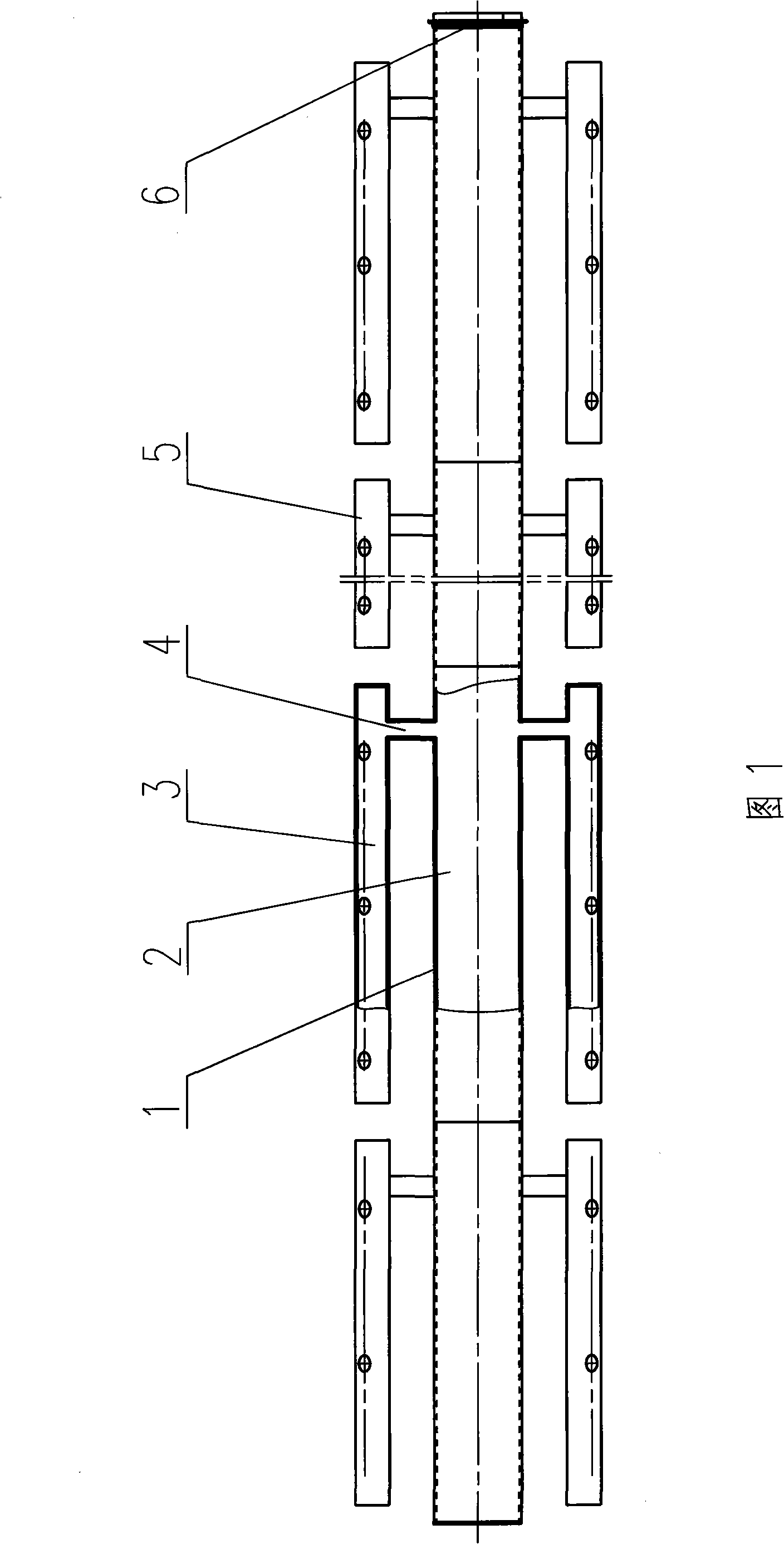
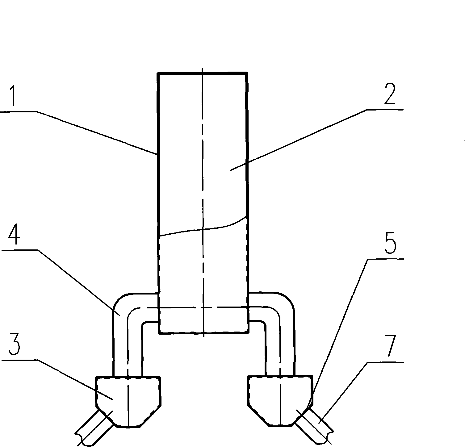
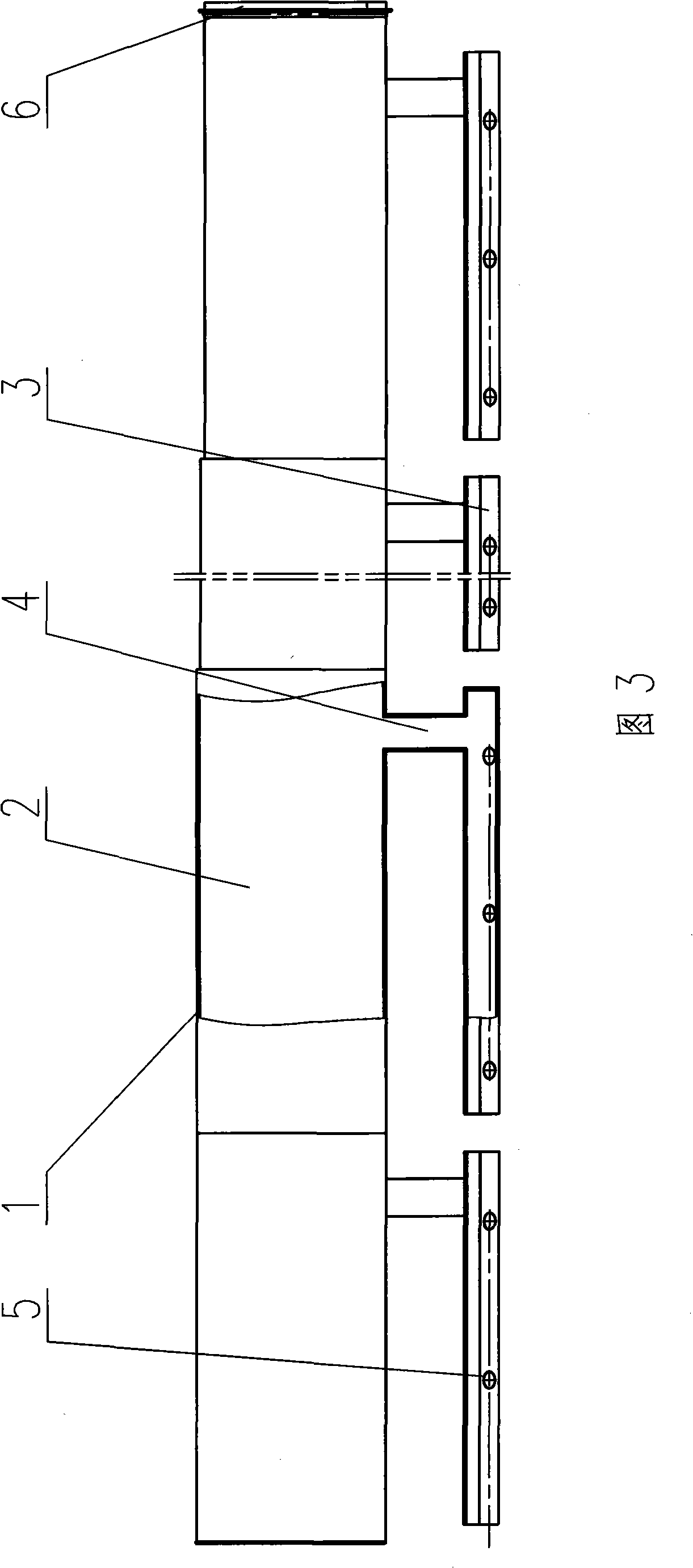
[0023] In Figure 1, figure 2 In the shown compact spinning suction duct with branch air ducts, the main suction duct 1 is a long duct with a rectangular section with a suction lumen 2, one end (tail end) of the long duct is closed, and the other end is the main air duct. A channel fan interface 6, the main air channel fan interface 6 is in sealing connection with the fan suction port. The main suction pipe 1 extends from the rear of the spinning frame to the head of the spinning frame, and its length is roughly equal to the length of the spinning frame. The main suction pipe 1 is formed by splicing several suction pipe sections in a sealed manner. The length of the main suction pipe 1 and the number of spliced ​​sections are determined according to the actual working length of the spinning frame. The cross-sectional sections of the main suction pipe 1 are equal. Thus having the same ventilation flow. Several suction branch pipes 3 are arranged symmetrically on both sides of ...


PUM


Abstract

The invention discloses a compact spinning air suction duct with branch air pipes, which consists of a main air suction pipe provided with an air suction pipe cavity and extending towards the two ends of the spinning machine, the main air suction pipe is communicated with at least two branch air suction pipes provided with centralized connecting pipe joints. The main air suction pipe not only can communicate with the branch air suction pipes through a main communicating pipe, but also can directly communicate with the branch air suction pipes through the communicating holes of the main and branch pipe walls. The invention has the advantages of less air negative pressure attenuation, little negative pressure difference between the air suction holes of centralized pipes, simple structure and convenient installation and utilization.

Description

technical field [0001] The invention relates to a ring spinning frame, in particular to a compact spinning ring spinning frame with a fiber accumulating device, in particular to the improvement of the compact spinning ring spinning frame collecting air suction device. Background technique [0002] In the traditional ring spinning frame, when the fiber bundle passes through the rear drafting zone and the front drafting zone of the drafting device of the ring spinning frame and reaches the nip of the front roller, the fiber strands are output to the twisting point where they are twisted into spun yarns. There is a spinning triangular area without twisting in between. Since the fibers in the spinning triangular area are basically out of control, the fibers are very easy to break away from and protrude from the triangular area and become fly and hairiness. In addition, the tension of the fibers in each part of the triangular area Inconsistent, ultimately affecting the strength i...

Claims


Application Information

Patent Timeline
Patent Type & Authority Applications(China)
IPC IPC(8): D01H5/72
Inventor 朱鹏曹小华王平王婵娟曹严严红霞
Owner DONGTAI TEXTILE MASCH CO LTD
Why Eureka
Try Eureka