
Laminar article for electrical use and a method and machine for producing said article

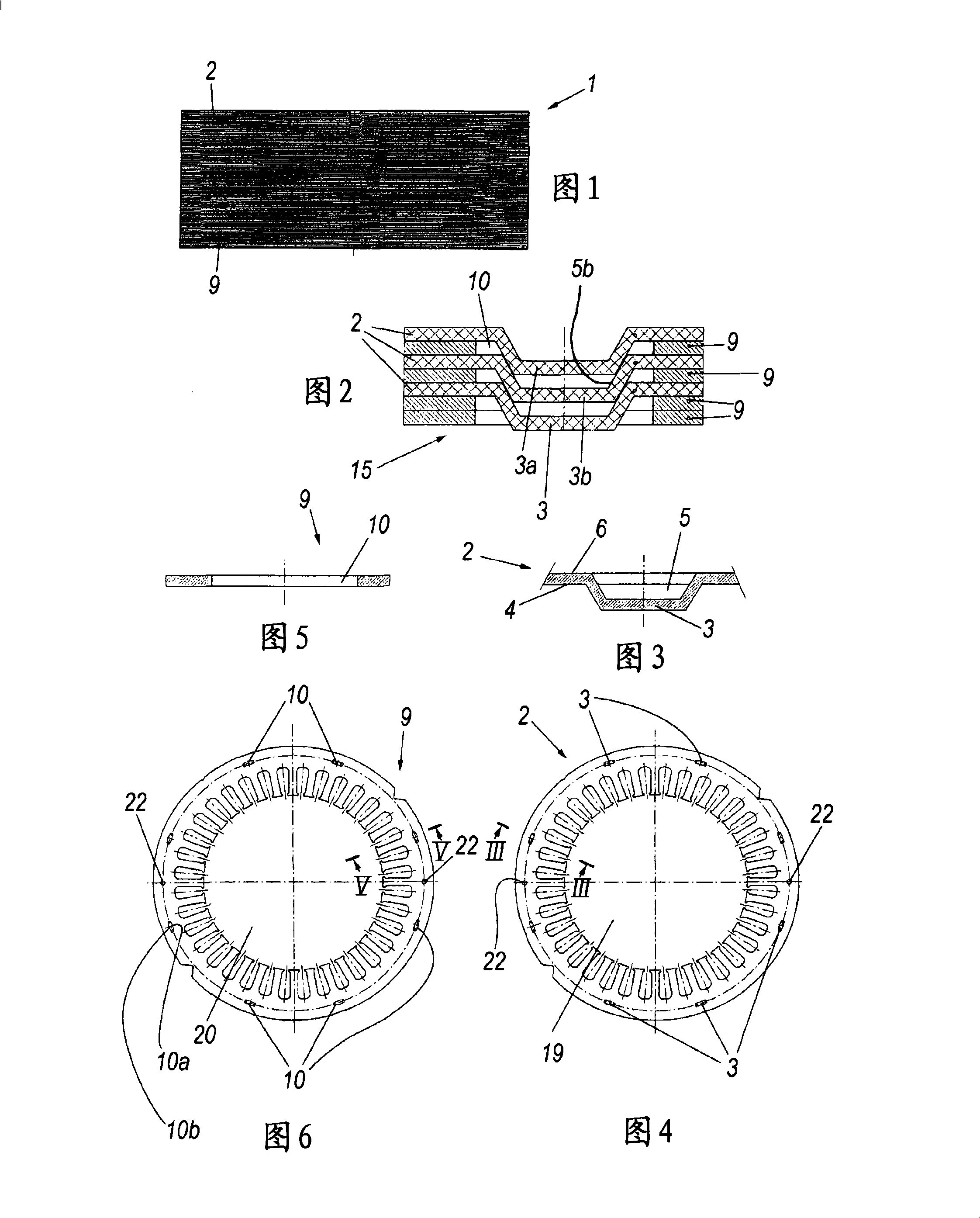
A layered product and electrical technology, which is applied in the direction of metal layered products, layered products, inductors/transformers/magnets, etc., can solve the problems of inability to ensure maintenance of helical angle lamination compensation, insufficient effectiveness, and complexity

Active Publication Date: 2008-11-05
CORRADA SPA
View PDF0 Cites 3 Cited by
  • Summary
  • Abstract
  • Description
  • Claims
  • Application Information

AI Technical Summary

Problems solved by technology

[0006] However, layered structures provided with the aforementioned laminations have likewise proven to be ineffective, since the height of the fastener must be related to the thickness of the laminations to ensure a proper connection is made
[0007] Furthermore, achieving a proper lamination helix and / or compensation with the aforementioned conventional systems has proven to be very complex (especially from an equipment point of view)
[0008] But the rotations applied to the laminations can also be very large (for example up to 180°), and especially for very tall layered structures, ie layered structures consisting of many stacked The offset between adjacent laminations is small, conventional systems cannot ensure that proper helix angles are maintained and / or compensate for all laminations, e.g. at their ends

Method used


Image

  • Laminar article for electrical use and a method and machine for producing said article
  • Laminar article for electrical use and a method and machine for producing said article
  • Laminar article for electrical use and a method and machine for producing said article

Examples


no. 1 example

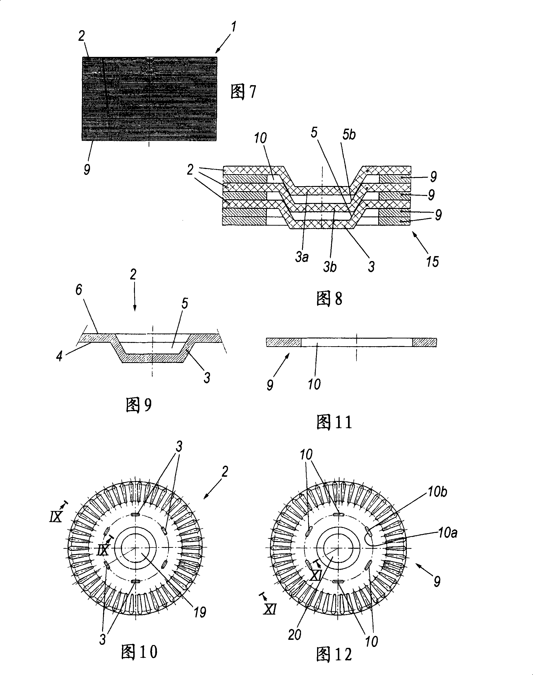
[0051] The rotor described in the first embodiment is, for example, a rotor of an electrical device such as a motor; it is shown in Figs. 7-12.

[0052] It comprises a plurality of first laminations 2 fixedly connected together with second laminations 9 interposed therebetween.

[0053] Each first lamination 2 has six fasteners 3 and the second lamination 2 correspondingly has six holes 10 which are interfered by fasteners 3 on both their inner circumferential side 10 a and outer circumferential side 10 b through.

[0054] A first end 15 has two mutually adjacent second laminations 9 held by fasteners 3 and the opposite end has two first laminations 2 held together directly by fasteners 3 and grooves 5 .

[0055]In this case, the diameter of the holes 19 in the first lamination 2 and the diameter of the holes 20 in the second lamination 9 are equal.

no. 2 example

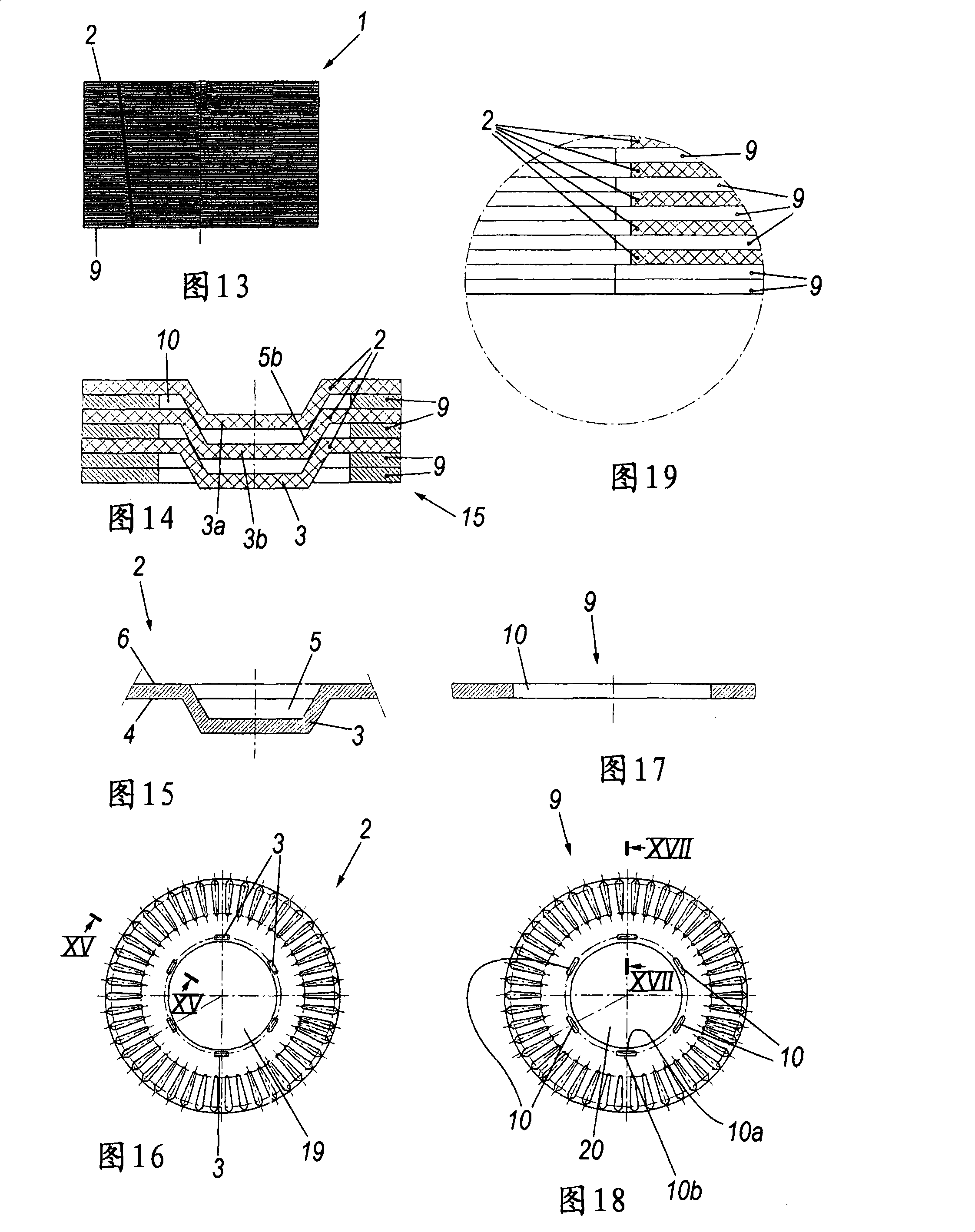
[0057] A rotor according to a second embodiment is shown in Figures 13-18.

[0058] It has a similar structure to the rotor described in the first embodiment.

[0059] In this case, however, the diameter of the hole 19 in the first lamination 2 is greater than the diameter of the hole 20 in the second lamination 9 .

[0060] The invention also relates to a method of manufacturing said layered product for electrical use.

[0061] The method involves die-cutting a plurality of laminations from a sheet metal, rotating and stacking the die-cut laminations, and then securing them together in a predetermined manner.

[0062] The laminations are punched with their reference axes rotated about the reference axis of the sheet metal through a predetermined angle to limit the rotation imparted to the laminations during their mutual fixation.

[0063] The invention also relates to a plant for the manufacture of said layered product for electrical use.

[0064] The apparatus comprises: ...


PUM


Abstract

The laminar article (1) for electrical use comprises a plurality of superposed first metal laminations (2) fixed together. Each of the first laminations (2) is provided with at least one fastener (3, 3a, 3b) projecting from a first surface (4) thereof and defining a recess (5, 5b) in its opposite side. Each fastener (3, 3a, 3b) of one lamination (2) is arranged to fit into a recess (5, 5b) of an adjacent lamination. The article presents second laminations (9) interposed between at least two adjacent first laminations (2) fixed together. The second laminations (9) are provided with through apertures (10) which are traversed by the fasteners (3, 3a, 3b) which fix the adjacent first laminations together. The method consists of die-cutting a plurality of laminations from a metal sheet, rotating the die-cut laminations and superposing them, to then fix them together in predetermined manner. The laminations can be die-cut with a reference axis thereof rotated through a predetermined angle about a reference axis of the metal sheet, to limit the rotations to be imposed on the laminations during their mutual fixing.

Description

technical field [0001] The invention relates to a layered product for electrical use, and also to a method and a device for manufacturing said layered product. Background technique [0002] Electrical devices, such as motors or transformers, usually consist of a magnetic circuit with a layered structure, ie a plurality of laminations stacked one above the other and fastened together. [0003] Specifically, the laminations are provided with fasteners formed by plastic deformation and protruding from the surface of the laminations so as to define protrusions on one side and bases on the other. Seats; traditionally, the laminations are held together by inserting the fasteners of one lamination into the base of the immediately adjacent lamination. [0004] However, this structure has a number of disadvantages including, inter alia, improper coupling of adjacent laminations together; in fact, due to the way the fastener / base pairing is formed, Leaving small air gaps prevents pr...

Claims


Application Information

Patent Timeline
Patent Type & Authority Applications(China)
IPC IPC(8): H01F27/26H01F27/245
CPCB21D28/22H02K15/02B32B15/00H02K2201/09B32B7/08H01F3/02H01F41/0233Y10T29/49117Y10T29/5137
Inventor G·贝尔托基G·加尔达尼尼D·博内蒂M·佩鲁基
Owner CORRADA SPA
Learn More