Image forming device

An imaging device and belt technology, applied in electrography, optics, instruments, etc., to achieve the effects of ensuring walking stability, simple adjustment, and prolonging life

Active Publication Date: 2012-01-11
FUJIFILM BUSINESS INNOVATION CORP
View PDF2 Cites 0 Cited by
  • Summary
  • Abstract
  • Description
  • Claims
  • Application Information

AI Technical Summary

Problems solved by technology

In such an image forming apparatus, belt members such as a conveyor belt for conveying a sheet and an intermediate transfer belt are stretched and run by at least two rollers, and thus have the ability to move toward any one of the axial directions of these two rollers while approaching. walking problem

Method used


Image

  • Image forming device
  • Image forming device
  • Image forming device

Examples


Embodiment Construction

[0033] Embodiments of the present invention will be described below with reference to the drawings.

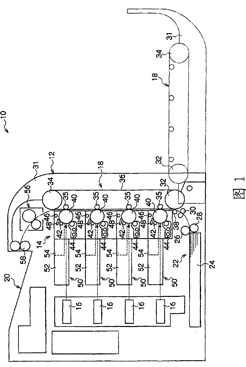
[0034] figure 1 An imaging device 10 according to an embodiment of the present invention is shown. The imaging device 10 has an imaging device main body 12 in which a photoreceptor unit 14 , an optical writing device 16 , and a transfer unit 18 are disposed. Also, a sheet discharge unit 20 is formed on the upper portion of the image forming apparatus main body 12 , and a sheet supply unit 22 is disposed on the lower portion of the image forming apparatus main body 12 .

[0035] The sheet supply unit 22 has a sheet cassette 24 that stores a plurality of sheets (recording media) in layers, and the sheet cassette 24 is detachably provided on the image forming apparatus main body 12 . A feed roller 26 is disposed on an upper portion of one end side of the sheet cassette 24 , and a retard roll 28 is provided to face the feed roller 26 .

[0036] The uppermost sheet in the sheet ...


PUM


Abstract

The invention provides an imaging device with a belt component for ensuring a long life of running stability. A location limit roller (74) and a driven roller (34) move along axial direction thereof with the help of an annular groove (76) under the condition that location of a projected wall (78) is deviated in width direction of a conveying belt (36), thus the stress on the projected wall (78) acting on the conveying belt (36) is within a preset value. Therefore, the conveying belt (36) may not move corresponding to the location deviation and snaking thereof is reduced showed by the solid line when location of the projected wall (78) of the conveying belt (36) has a big deviation. Moreover, problems such as rupture etc. of the projected wall (78) are reduced because the stress more than necessary is not acted on the projected wall (78). The invention is able to prolong service life of the conveying belt (36), comparing to the imaging device (10) not using this.

Description

technical field [0001] The present invention relates to an image forming apparatus having a belt member tensioned by at least two rollers. Background technique [0002] Conventionally, an image forming apparatus is known that forms an image by transferring and fixing a toner image transferred onto an intermediate transfer belt with a photoreceptor (image holder) to a sheet (recording medium). In such an image forming apparatus, belt members such as a conveyor belt for conveying a sheet and an intermediate transfer belt are stretched and run by at least two rollers, and thus have the ability to move toward any one of the axial directions of these two rollers while approaching. walking problem. [0003] Therefore, for example, in Japanese Patent Application Laid-Open No. 2004-45959, ribs are protruded along the running direction of the belt member on the inner surface (rear surface) on the side of one end in the width direction of the belt member. A groove that engages with ...

Claims


Application Information

Patent Timeline
Patent Type & Authority Patents(China)
IPC IPC(8): G03G15/16
Inventor 井出典孝森本茂
Owner FUJIFILM BUSINESS INNOVATION CORP
Why Eureka
Try Eureka