Fourier transform interference spectrometer based on slow ray light velocity controlling technology

A Fourier transform and spectrometer technology, applied in the field of Fourier transform interference spectrometer, can solve the problems of inability to completely eliminate, limit the resolution of the spectrometer, and increase the volume, so as to overcome vibration and external disturbance, improve spectral resolution, The effect of improving stability

Inactive Publication Date: 2008-10-29
HARBIN INST OF TECH
View PDF0 Cites 7 Cited by
  • Summary
  • Abstract
  • Description
  • Claims
  • Application Information

AI Technical Summary

Problems solved by technology

However, regardless of the air bearing method or the mechanical bearing method, the slight tilt or vibration interference during the movement of the moving mirror will affect the two mirrors not being completely vertical. More complex, larger size, inconvenient operation
In addition, the moving distance and speed of the moving mirror will affect the resolution of the interferometer. In theory, the longer the moving distance, the better the resolution. However, the moving range of the moving mirror of the traditional interferometer is limited by the volume of the instrument, and it is impossible to achieve a few meters or even tens of meters long, which further limits the resolution of the spectrometer

Method used


Image

  • Fourier transform interference spectrometer based on slow ray light velocity controlling technology
  • Fourier transform interference spectrometer based on slow ray light velocity controlling technology

Examples


Embodiment 1

[0013] Embodiment 1, with reference to FIG. 1 , the innovation of the present invention lies in the part of controlling the optical path difference. The comparison between the traditional structure and the new structure is shown in Figure 1. In the figure: 1: incident light; 2: beam splitter; 3: detector; 4: fixed mirror; 5: moving mirror; 6: tunable slow light medium; 7: light speed control system. In the new structure, a series of problems caused by controlling the reflector 5 are avoided (mostly because the changeable range of the optical path difference is limited due to the limited moving distance of the reflector, and the resolution cannot be improved). The moving mirror control system and the dynamic collimation system in the traditional spectrometer are replaced by the slow light medium 6 and the light speed control system 7, which improves the resolution and stability.

Embodiment 2

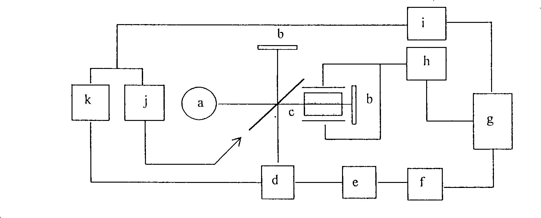
[0014] Embodiment 2, with reference to FIG. 2 , the light emitted by the light source a passes through the beam splitter and is split into two paths of light. One way directly hits the reflector b, and the other way first passes through the slow-light medium c, and then hits the reflector b. These two paths of light reflect and return to the beam splitter, where they interfere with each other. The interferogram is received by detector d. The received signal is amplified by the filter amplifier e, and input to the computer g after the A / D converter f. The optical path difference of the two paths of light in the interferometer is controlled by a control signal sent by the computer and controlled by the light speed controller h. At the same time, the computer g can manually control the band, and select and control the response band of the beam splitter and the controller through the band controller i.


PUM


Abstract

The invention aims to provide a Fourier transformation interferometer spectrometer of high spectral resolution, small volume and high stability. The spectrometer can be used for measuring spectrum and is based on the slow light velocity controllable technology. The spectrometer changes the traveling time of light in limited distance by utilizing the slow light technology, that is, utilizing the technology to change the optical path difference between two light paths on the part of interferometer in the spectrometer and enlarging the optical path difference, thus obviously improving the spectrum sensitivity of the spectrometer, eliminating a control system and a collimating system required for moving a reflecting mirror, simplifying the spectrometer, eliminating vibration and positioning error and improving stability.

Description

technical field [0001] The invention relates to an optical instrument, in particular to a Fourier transform interference spectrometer based on the technology of slow light speed controllable. technical background [0002] The core part of the Fourier transform spectrometer is the interferometer, which determines the highest resolution and other performance indicators of the spectrometer. Whether it is an air bearing interferometer, a mechanical bearing interferometer, or a double moving mirror mechanical rotating interferometer, the optical path of one of the two paths of light is required to change, and this requirement is usually achieved by moving the moving mirror. However, the formation of interference between the two beams requires that the moving mirror and the fixed mirror be strictly perpendicular. However, regardless of the air bearing method or the mechanical bearing method, the slight tilt or vibration interference during the movement of the moving mirror will a...

Claims


Application Information

Patent Timeline
Patent Type & Authority Applications(China)
IPC IPC(8): G01J3/45G01J3/02
Inventor 掌蕴东具香春袁萍
Owner HARBIN INST OF TECH
Why Eureka
Try Eureka