Needle bearing holder structure for engine
A technology of needle roller bearings and cages, which is applied in the field of bearing components, can solve problems affecting engine performance, crank and connecting rod locking, and engine scrapping, so as to avoid needle roller jamming, prevent wear and deformation, and ensure performance Effect
Inactive Publication Date: 2008-10-29
力帆科技(集团)股份有限公司
View PDF0 Cites 1 Cited by
- Summary
- Abstract
- Description
- Claims
- Application Information
AI Technical Summary
Problems solved by technology
Because the thickness of the beam is smaller than that of the outer ring, the force is weaker, so the longer the engine is used, the degree of wear of the beam will increase, and finally lead to deformation of the beam, which not only affects the performance of the engine, but also easily causes the needle roller to be stuck. , crank connecting rod lock, etc., which will cause the engine to be scrapped
Method used
View moreImage
Smart ImageViewing Examples

Examples
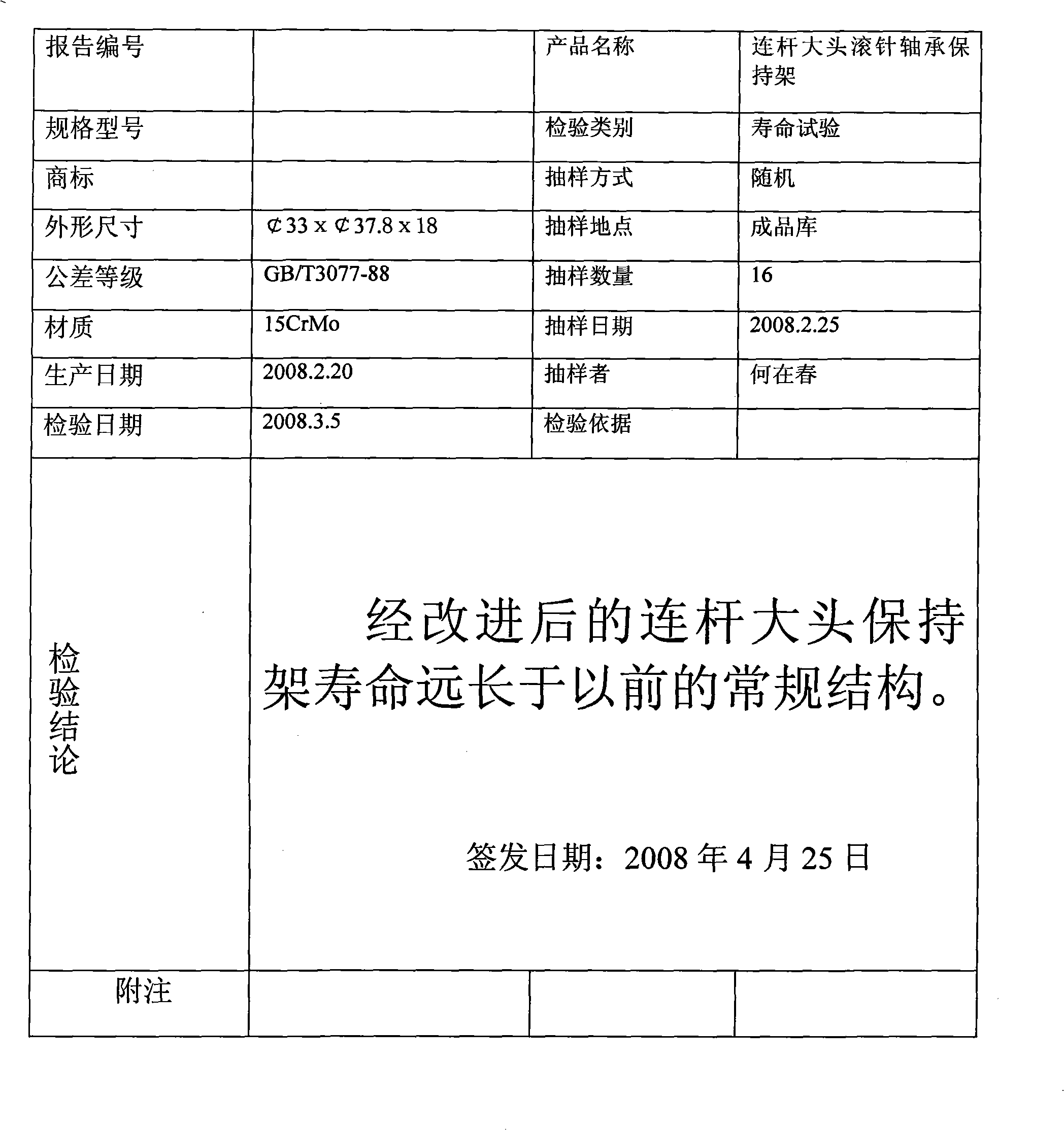
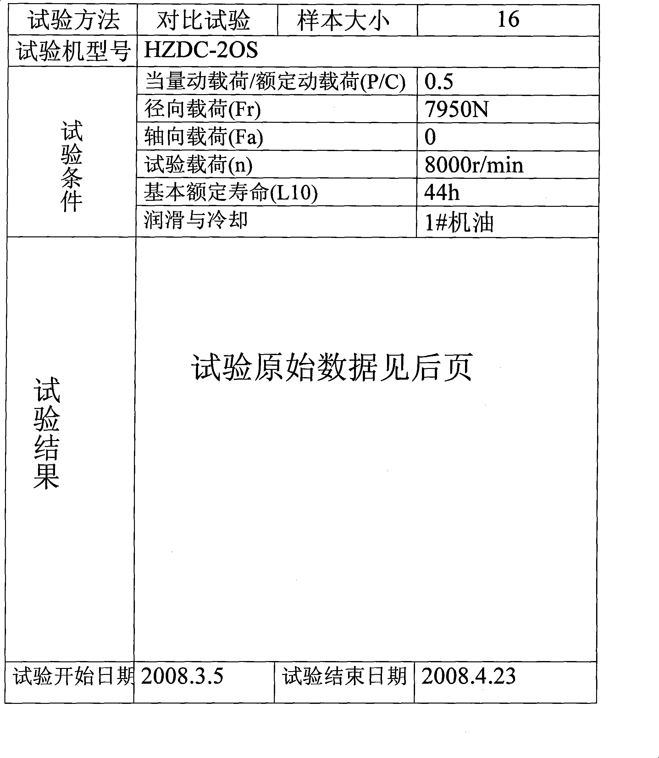
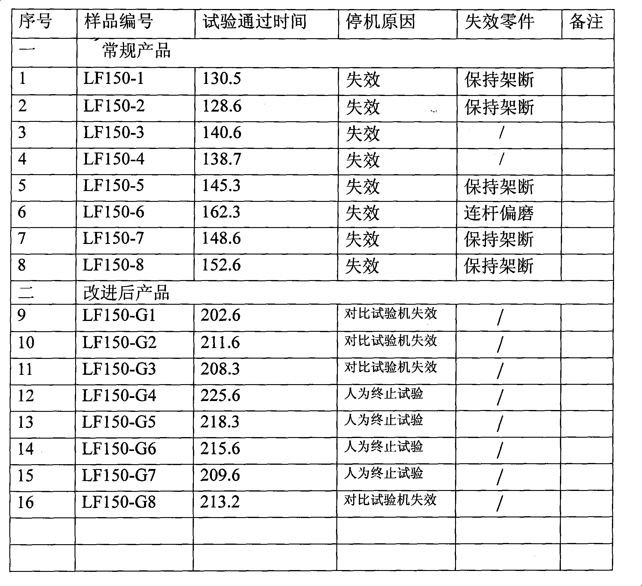
Embodiment Construction
Login to View More PUM
 Abstract
The invention discloses a motor used needle bearing cage structure which comprises two parallelly arranged outer rings (1) and beams (9) connecting the two outer rings (1); wherein the beams are uniformly distributed circumferentially; a through groove (3) is opened along the width direction on the top surface of the beam (2); two lateral walls of the through groove (3) are respectively close to inner end surfaces of the two outer rings (1). By slightly modifying the beam, the structure can effectively prevent the needle bearing cage from wearing and deforming and greatly improve the service performance of a crank-connecting rod and an entire motor. The structure is characterized by ingenious design, simple structure, easy implementation, etc.
Description
technical field The invention relates to a bearing component, in particular to a needle roller bearing cage structure for an engine. Background technique The crankpin of the engine crank and the big end of the connecting rod are generally connected by a needle bearing. Under the action of the needle roller embedded in the needle bearing cage, the connecting rod and the crank can rotate relatively, so that the connecting rod will act on the piston. The force is transmitted to the crank, so that the reciprocating linear motion of the piston is converted into the rotary motion of the crank. The commonly used needle roller bearing cage is composed of two outer rings arranged in parallel and several beams located between the two outer rings. The beams are evenly distributed on the circumference. The top surface of the beam is on the same circumference as the outer peripheral surface of the outer ring. It is found in practice that after the engine has been running for a period o...
Claims
Login to View More Application Information
Patent Timeline
 Patent Type & Authority Applications(China)
IPC IPC(8): F16C33/46
Inventor 肖凤军李家奇辛琪李力
Owner 力帆科技(集团)股份有限公司
Features
- R&D
- Intellectual Property
- Life Sciences
- Materials
- Tech Scout
- Unparalleled Data Quality
- Higher Quality Content
- 60% Fewer Hallucinations
Learn More Browse by: Latest US Patents, China's latest patents, Technical Efficacy Thesaurus, Application Domain, Technology Topic, Popular Technical Reports.
© 2025 PatSnap. All rights reserved.Legal|Privacy policy|Modern Slavery Act Transparency Statement|Sitemap|About US| Contact US: help@patsnap.com