
Assembling jig for acceptor and pilot valve body in electro-hydraulic servo valve and method thereof

A technology of electro-hydraulic servo valves and assembly fixtures, which is applied in the direction of manufacturing tools, workpiece clamping devices, metal processing, etc., can solve the problems of low assembly quality, large gap in technical level, poor operability, etc., and achieve good assembly quality and use Long life and high positioning accuracy

Inactive Publication Date: 2008-10-29
SHANGHAI NUOMA HYDRAULIC SYST
View PDF0 Cites 6 Cited by
  • Summary
  • Abstract
  • Description
  • Claims
  • Application Information

AI Technical Summary

Problems solved by technology

However, the research and manufacture of domestic servo valves are still in a relatively backward state, and the technical level of the combination and assembly of parts is also far behind that of foreign countries.
For the assembly of the existing electro-hydraulic servo valve, there are also many problems and defects. Many parts are difficult to assemble and the operability is poor. In particular, the assembly method of the receiver and the pilot valve body has low assembly quality and low yield. Failure to meet the requirements of design drawings, such as shape and position tolerances (parallelism, perpendicularity, symmetry, coaxiality, etc.), smoothness, results in repetitive work, and in severe cases, parts or components will be scrapped, wasting manpower, material resources, and financial resources , and further adversely affect the performance of the entire product. The poor test results after assembly will directly affect the overall performance of the electro-hydraulic servo valve and affect the efficiency of the factory.

Method used


Image

  • Assembling jig for acceptor and pilot valve body in electro-hydraulic servo valve and method thereof
  • Assembling jig for acceptor and pilot valve body in electro-hydraulic servo valve and method thereof

Examples


Embodiment Construction

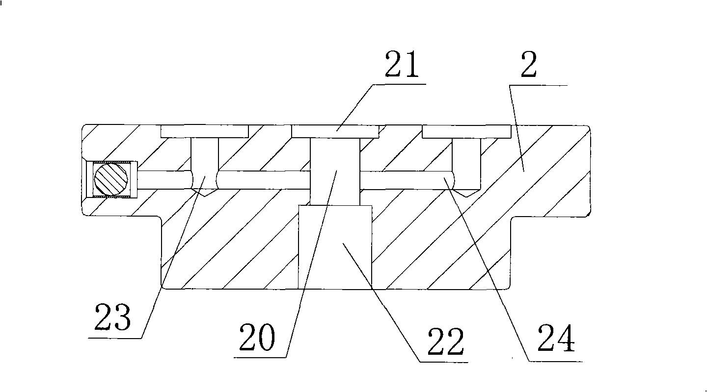
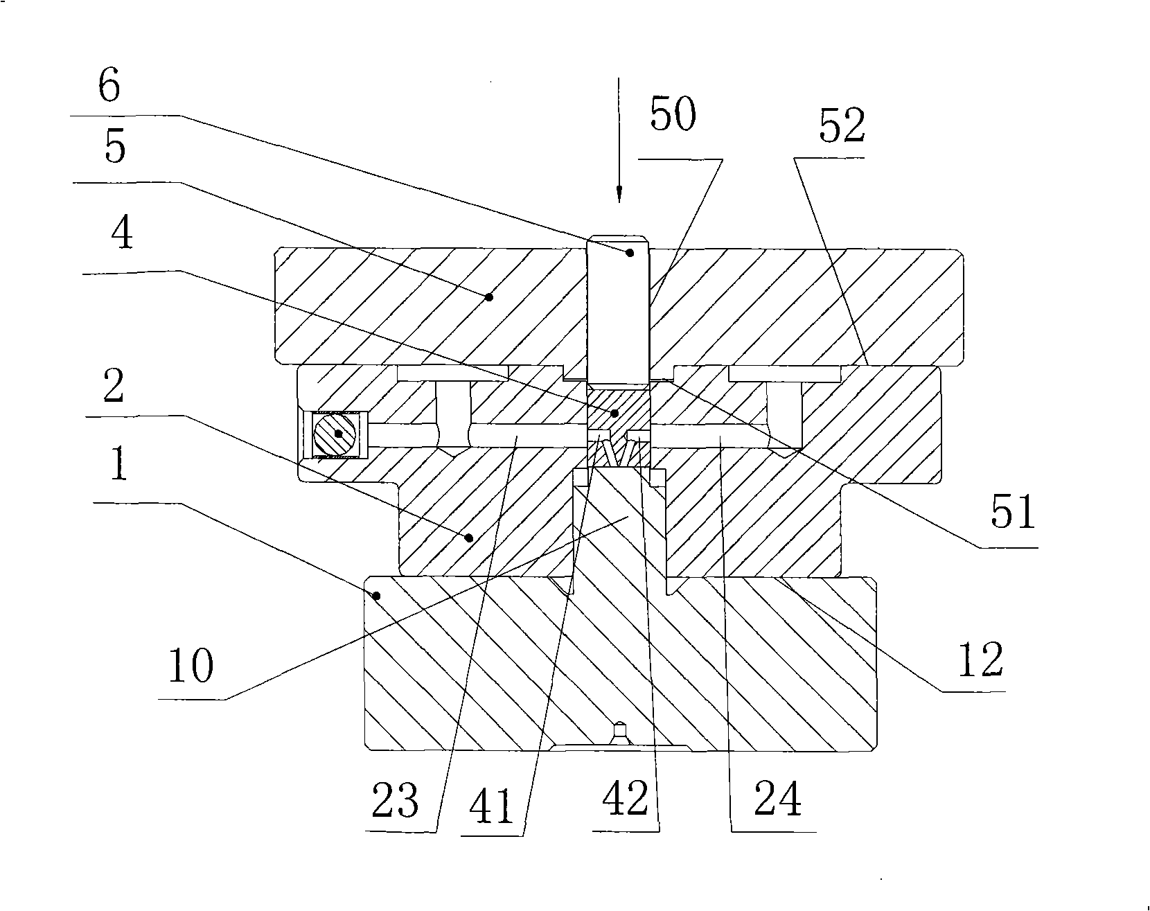
[0013] see figure 1 , figure 2 , the assembly fixture used for the receiver and the pilot valve body in the electro-hydraulic servo valve of the present invention includes an upper positioning block 5, a lower positioning block 1, a pilot valve body 2 and a pressure rod 6. Wherein, the pilot valve body 2 has upper and lower assembly holes 21 , 22 and a receiver cavity 20 , and the receiver cavity 20 has a flat surface opposite to the reference surface of the receiver 4 . The lower positioning block 1 is an inverted T-shaped block, and the shape of the outer end of its vertical rod 10 matches that of the lower assembly hole 22 of the pilot valve body 2 . The upper positioning block 5 is a block body, and the center of its end face is provided with a press-fit through hole 50 consistent with the diameter of the outer end of the receiver 4, and a positioning boss 51 that can be embedded in the assembly hole 21 of the pilot valve body 2 is provided on the lower end face. The pr...


PUM


Abstract

The invention discloses an assembly clamp of a receiver and a pilot valve body in an electrohydraulic servo valve which includes an upper location block, a lower location block, the pilot valve body provided with an upper assembly hole, a lower assembly hole and the inner cavity of the receiver and a pressure rod; the lower location block is a reversed T-shaped block; the shape of the outer end of a vertical rod of the lower location block is matched with the lower assembly hole of the pilot valve body; the upper location block is a plate block body and the center of the end surface of the upper location block is provided with a compact through hole which has the consistent diameter of the outer end of the receiver; besides, a location lug boss which can be embedded into the upper assembly hole of the pilot valve body is arranged on the lower end surface of the upper location block; the pressure rod is inserted into the compact through hole of the upper location block; can lead the receiver in the inner cavity of the receiver mounted on the pilot valve body to be pressed to the preset position and can lead the working channel of the pilot valve body to be communicated with the inner channel of the receiver. The assembly clamp of the receiver and the pilot valve body in the electrohydraulic servo valve of the invention and the method thereof are adopted, so the clamp has the advantages of high location precision, good assembly quality, good maneuverability, high commonality and long service life, etc.

Description

technical field [0001] The invention relates to a machining fixture for precision small parts, in particular to an assembly fixture for a receiver and a pilot valve body in an electro-hydraulic servo valve and a method thereof. Background technique [0002] The development of electro-hydraulic servo valves in the international professional field has gone through more than 50 years, and the application occasions are becoming more and more extensive. However, the research and manufacture of domestic servo valves are still in a relatively backward state, and the technical level of the combination and assembly of parts is also far behind that of foreign countries. For the assembly of the existing electro-hydraulic servo valve, there are also many problems and defects. Many parts are difficult to assemble and the operability is poor. In particular, the assembly method of the receiver and the pilot valve body has low assembly quality and low yield. Failure to meet the requirement...

Claims


Application Information

Patent Timeline
IPC IPC(8): B25B11/02B23P11/02B23P19/02
Inventor 曹勇吴越黄周成
Owner SHANGHAI NUOMA HYDRAULIC SYST
Learn More