
Luminance compensating mechanism and method for backlight module

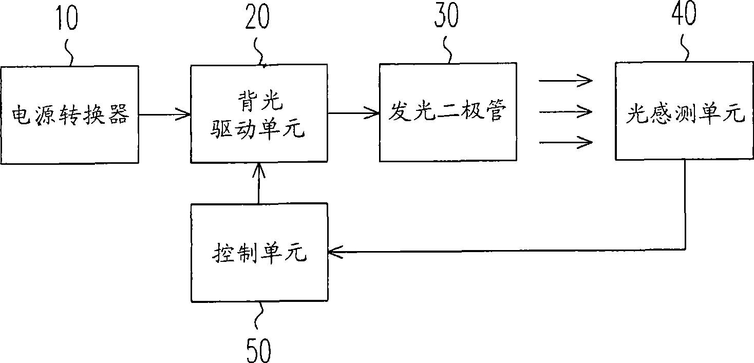
A technology of brightness compensation and backlight module, applied in the field of brightness compensation device, can solve the problems of increased cost of control unit, limited brightness effect of light emitting diode 30, etc.

Inactive Publication Date: 2010-11-03
NOVATEK MICROELECTRONICS CORP
View PDF11 Cites 0 Cited by
  • Summary
  • Abstract
  • Description
  • Claims
  • Application Information

AI Technical Summary

Problems solved by technology

Not only need to spend additional cost to increase the control unit 50, but also the effect of adjusting the brightness of the light emitting diode 30 is quite limited

Method used


Image

  • Luminance compensating mechanism and method for backlight module
  • Luminance compensating mechanism and method for backlight module
  • Luminance compensating mechanism and method for backlight module

Examples


Embodiment Construction

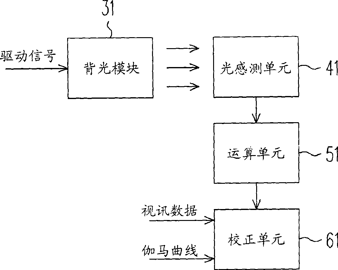
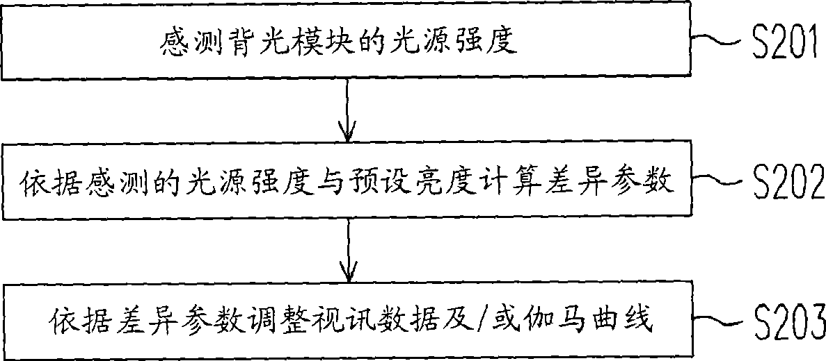
[0050] Figure 2A is a structural diagram of a brightness compensation device for a backlight module according to the first embodiment of the present invention, Figure 2B It is a flowchart of a brightness compensation method for a backlight module according to the first embodiment of the present invention, please refer to Figure 2A and Figure 2B . The brightness compensation device includes a light sensing unit 41 , a computing unit 51 , and a correction unit 61 . The brightness compensation device is suitable for compensating the brightness of the backlight module 31 of the display device. The backlight source of the backlight module 31 emits corresponding light according to the voltage and current. In addition, in this embodiment, the backlight source of the backlight module 31 is particularly illustrated by taking red green blue (RGB for short) LEDs as an example to illustrate this embodiment. Those skilled in the art should understand that the "RGB LED" mentioned in...


PUM


Abstract

The invention discloses a device and a method for the luminance compensation of a backlight module. The device and the method makes use of a light sensing unit to measure the light source intensity of the backlight module, and calculates a difference parameter according to the light source intensity and preset luminance; then, a gamma curve, video data or the light source intensity of the backlight module are adjusted according to the difference parameter so as to reduce the influence on display quality due to the changes of the backlight module caused by temperature or aging.

Description

technical field [0001] The invention relates to a brightness compensation device of a backlight module, in particular to a method for compensating the brightness of the backlight module by using light sensing technology. Background technique [0002] With the advancement of technology, liquid crystal displays (LCD for short) are becoming more and more popular. However, the liquid crystal display will age with time, especially the backlight module of the liquid crystal display. Some backlight modules mainly use light-emitting diodes (Light-Emitting Diodes, referred to as LEDs) to provide light sources. The intensity of light emitted by LEDs will change due to temperature and aging of components. In order for the liquid crystal display to display stable brightness and color, it is necessary to compensate the color and brightness of the backlight module as the backlight module ages. [0003] figure 1 It is a structure diagram of a known brightness compensation device for a ...

Claims


Application Information

Patent Timeline
Patent Type & Authority Patents(China)
IPC IPC(8): G09G3/34H05B33/00G02F1/13357H05B37/02
Inventor 魏献旺
Owner NOVATEK MICROELECTRONICS CORP
Learn More