Large wind barn small air scoop crossbeam type chain-grate

A technology of chain grate and air bucket, which is applied in the direction of mobile grate, grate, lighting and heating equipment, etc. It can solve the problems of reducing combustion efficiency, uneven air distribution, and affecting combustion, so as to improve combustion quality and supply power. The effect of uniform wind and reduced wind speed

Inactive Publication Date: 2011-05-18
瓦房店市永宁机械厂
View PDF0 Cites 0 Cited by
  • Summary
  • Abstract
  • Description
  • Claims
  • Application Information

AI Technical Summary

Problems solved by technology

[0002] At present, the combustion equipment used in large boilers is mainly beam type chain grate. The structure of beam type chain grate is a frame composed of middle beam, upper guide rail and lower guide rail. Connected with the driving device, each independent air chamber is formed under the upper furnace chain and between the adjacent center beams, and the air is supplied in sections through each independent air chamber and the air supply device connected to the air chamber. This structure Due to the high wind speed entering the grate, the large proportion of dynamic pressure, and the existence of serious wind diffusion and eddy currents, etc., the air distribution on the grate surface is uneven, and the wider the grate is, the more obvious this phenomenon is. Affect combustion, reduce combustion efficiency, and waste coal resources
[0003] The existing beam-type chain grate adopts ordinary plate-type wall panels with air inlets connected to the air supply device. The area of ​​the air inlets is smaller than the cross-sectional area of ​​each air chamber. The change of static pressure distribution caused by the diffusion of airflow can also lead to uneven air distribution

Method used


Image

  • Large wind barn small air scoop crossbeam type chain-grate
  • Large wind barn small air scoop crossbeam type chain-grate
  • Large wind barn small air scoop crossbeam type chain-grate

Examples


Embodiment Construction

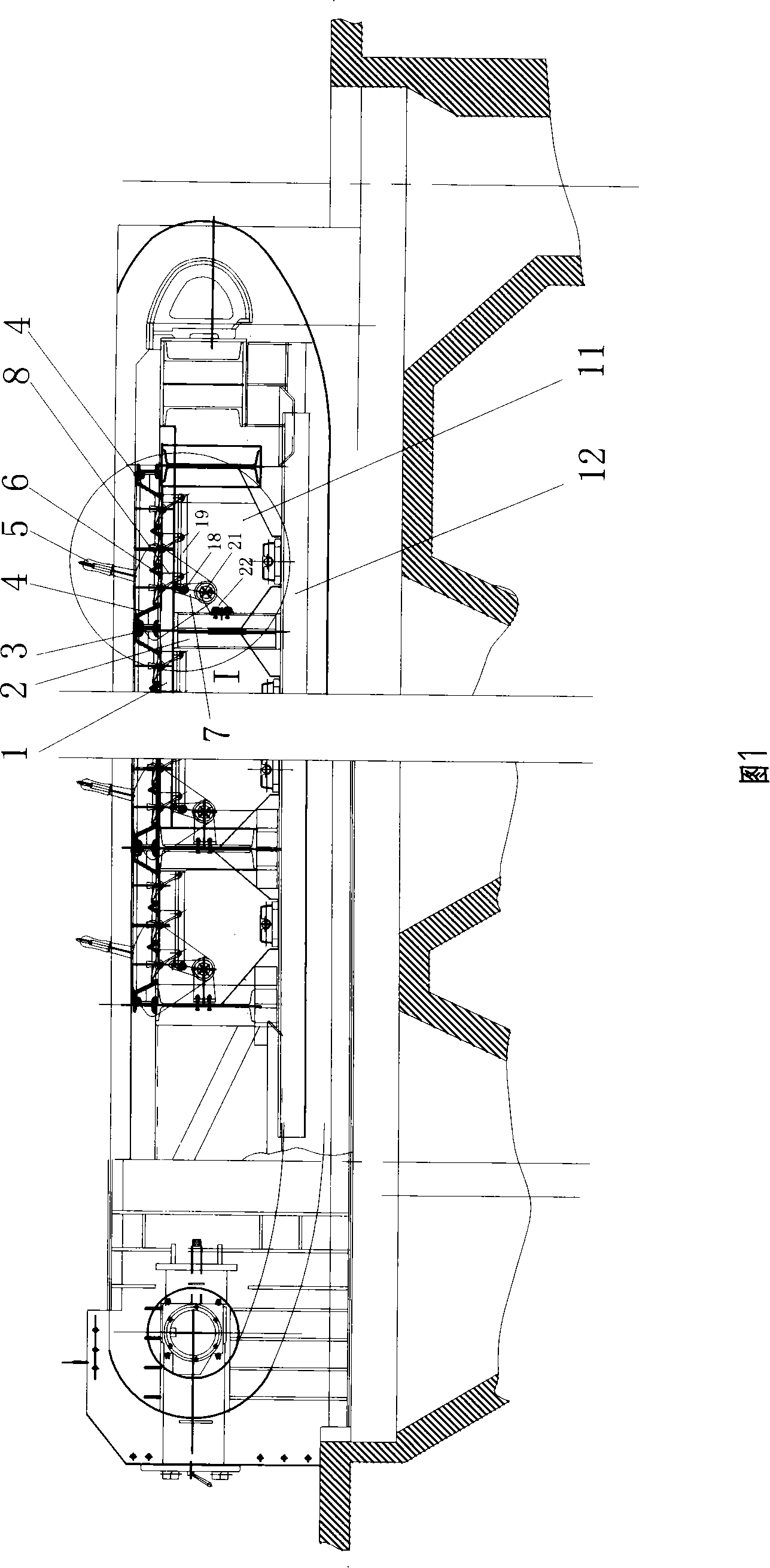
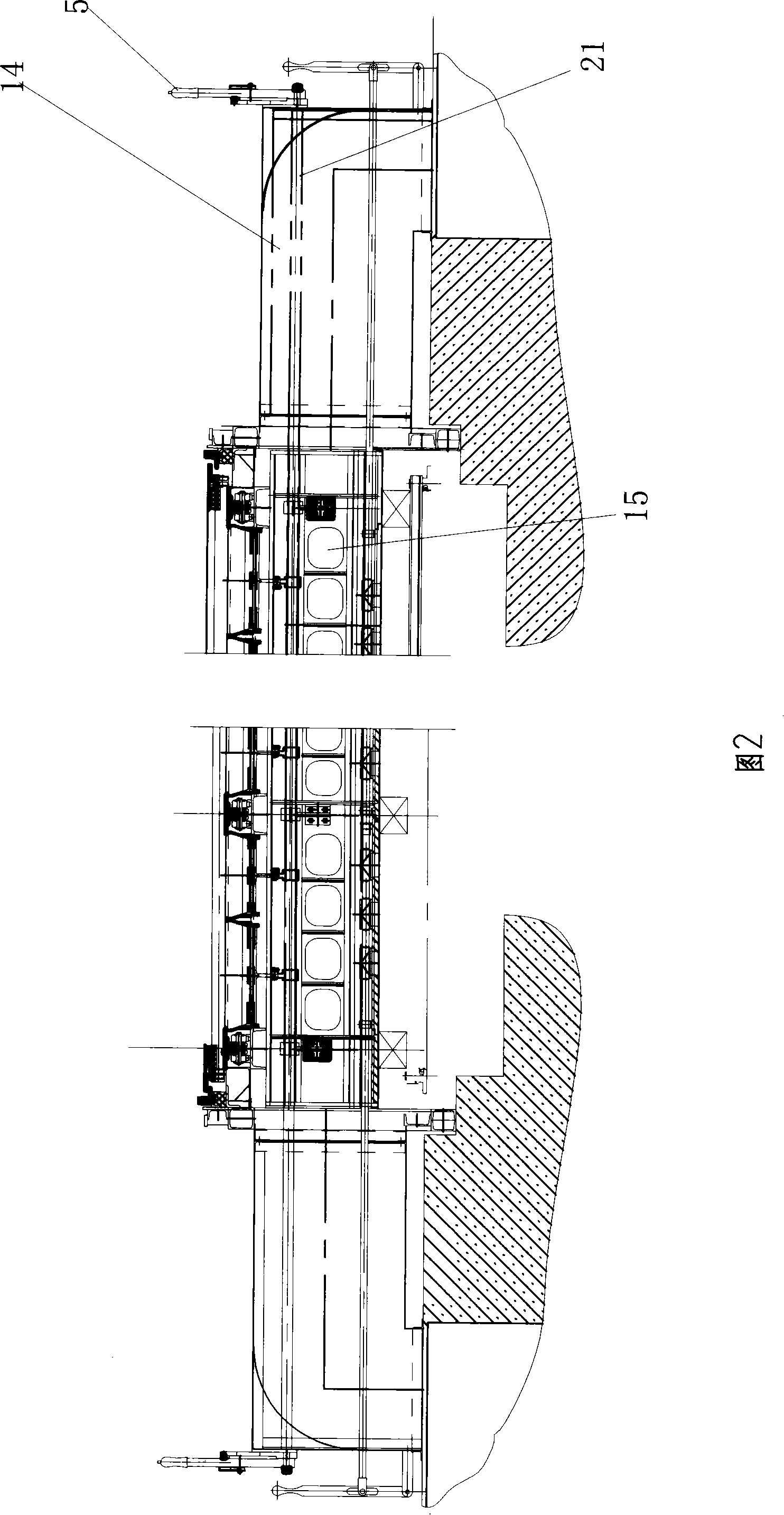
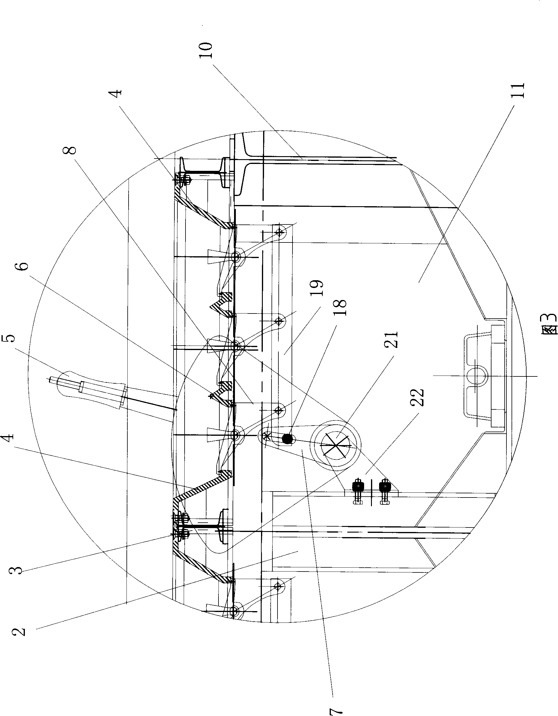
[0014] As shown in the figure: 2 is the middle beam, 1 is the upper guide rail, and 12 is the lower guide rail. The frame is composed of the middle beam 2, the upper guide rail 1 and the lower guide rail 12, and the furnace chain connected with the driving device is installed on the frame. When the furnace chain forms a ring shape and rotates, the fuel is located above the upper furnace chain. Interconnected wind bins 11 are formed under the upper furnace chain, that is, each center beam 2 is processed with a through hole 15, and the area between adjacent center beams 2 communicates with each other through the through hole 15, forming a An integral large air chamber 11 is quite different from an independent air chamber formed between each center beam 2 in the prior art. There is the bellows 14 that communicates with the wind storehouse 11 on all the sides of both sides of the whole fire grate, and the bellows 14 connects the air supply device. When working, the air supply dev...


PUM


Abstract

The invention discloses an endless grate, in particular to a big wind bin and small wind catcher crossbeam-type endless grate. The endless grate comprises a frame consisting of a middle beam (2), an upper lead rail (1) and a lower lead rail (12); a furnace chain connected with a drive device is arranged on the frame; the endless grate is characterized in that: the lower part of the furnace chain on the upper part is provided with a wind bin (11) communicated with the furnace chain; a wind chest (14) communicated with the wind bins (14) is arranged on the whole side of the grate; the wind chest (14) is connected with a wind supply device. The endless grate changes the mode that each wind chamber respectively supplies wind in the prior art, thereby greatly reducing wind speed, stabilizing wind pressure, ensuring the even wind supply to the furnace chain, improving the burning quality of fuel and saving energy.

Description

technical field [0001] The invention relates to a chain fire grate, in particular to a chain fire grate with a large wind bin and a small wind bucket beam type. Background technique [0002] At present, the combustion equipment used in large boilers is mainly beam type chain grate. The structure of beam type chain grate is a frame composed of middle beam, upper guide rail and lower guide rail. Connected with the driving device, each independent air chamber is formed under the upper furnace chain and between the adjacent middle beams, and the air is supplied in sections through each independent air chamber and the air supply device connected to the air chamber. This structure Due to the high wind speed entering the grate, the large proportion of dynamic pressure, and the existence of serious wind diffusion and eddy currents, the air distribution on the grate surface is uneven, and the wider the grate is, the more obvious this phenomenon is. It affects combustion, reduces com...

Claims


Application Information

Patent Timeline
Patent Type & Authority Patents(China)
IPC IPC(8): F23H11/02F23H11/10
Inventor 刘玉振
Owner 瓦房店市永宁机械厂
Why Eureka
Try Eureka