
Large rod-cable extending arm extension driving mechanism

A technology of driving mechanism and extending arm, which is applied in the direction of motor vehicles, space navigation equipment, space navigation vehicles, etc., can solve the problem of low processing precision of four-thread spiral sleeve, high manufacturing precision, high manufacturing process requirements, and spiral sleeve rotary support. Difficult to achieve and other problems, to achieve the effect of light weight, low processing and manufacturing process requirements, and simple structure

Inactive Publication Date: 2008-10-22
BEIJING INST OF SPACECRAFT SYST ENG +1
View PDF0 Cites 10 Cited by
  • Summary
  • Abstract
  • Description
  • Claims
  • Application Information

AI Technical Summary

Problems solved by technology

[0003] The purpose of the present invention is to provide a large-scale cable-rod type extension arm expansion drive mechanism, which can solve the problem that the expansion and retraction of the existing large-scale cable-rod type extension arm is driven by a four-thread spiral lifting sleeve type mechanism, which has manufacturing accuracy, High manufacturing process requirements, low machining accuracy or deformation of the four-thread spiral sleeve will cause the cable-rod extension arm to "stuck", difficult to realize the rotary support of the spiral sleeve, and expensive manufacturing costs

Method used


Image

  • Large rod-cable extending arm extension driving mechanism
  • Large rod-cable extending arm extension driving mechanism
  • Large rod-cable extending arm extension driving mechanism

Examples


specific Embodiment approach 1

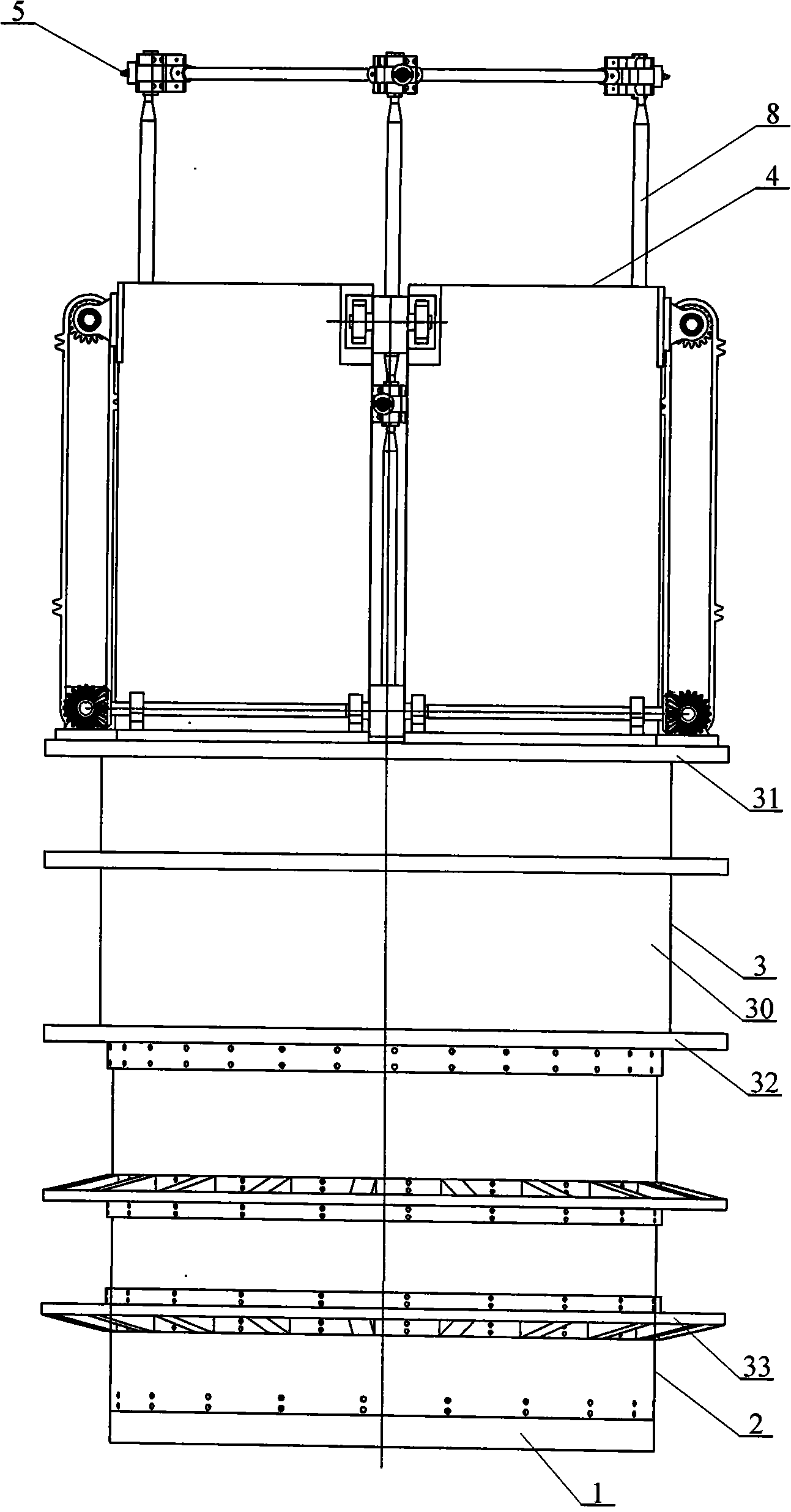
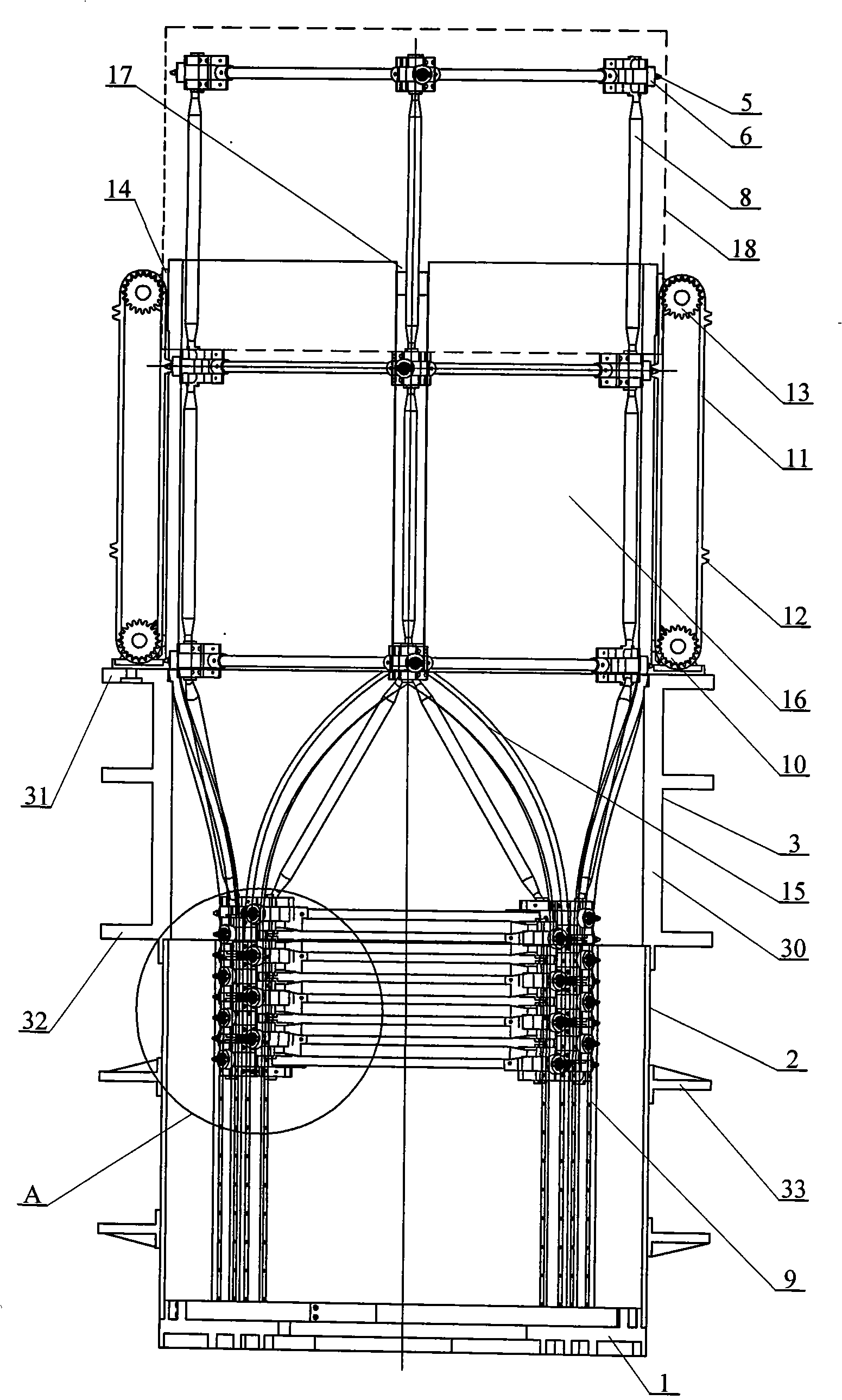
[0007] Specific implementation mode one: combine Figure 1 to Figure 8 This embodiment is described. This embodiment consists of a bottom end cover 1, a retracting sleeve 2, a derotation sleeve 3, four sets of chain lifting mechanisms, a driving sleeve 4, an extension arm tooth piece 5, a roller 6, and a cable rod type extension arm assembly, eight linear tracks 9 and a reversing transmission mechanism; each group of chain lifting mechanisms is composed of a driving sprocket 10, a chain 11, a chain tooth 12, a driven sprocket 13, and a sprocket support 14; The bottom end cover 1, the retracting sleeve 2, the derotation sleeve 3, and the driving sleeve 4 are fixedly connected together from bottom to top in order to provide a container for the cable rod type extension arm in the folded state. The cloth is provided with four groups of curved grooves, each group of curved grooves is composed of two symmetrically arranged curved grooves 15, and the inner wall of the retracting slee...

specific Embodiment approach 2

[0008] Specific implementation mode two: combination Figure 5 To illustrate this embodiment, the reversing transmission mechanism of this embodiment is composed of a motor 19, a first short transmission shaft 20, a second short transmission shaft 21, a first long transmission shaft 22, a second long transmission shaft 23, and a bevel gear pair 24 ; The first short transmission shaft 20, the second short transmission shaft 21, the first long transmission shaft 22 and the second long transmission shaft 23 are respectively fixed with the driving sprocket 10, and the motor 19 and the first short transmission shaft 20 drive connection, between the first short transmission shaft 20 and the first long transmission shaft 22, between the first long transmission shaft 22 and the second long transmission shaft 23 and between the second long transmission shaft 23 and the second short transmission shaft 21 respectively The driving ring is formed through the transmission connection of the ...

specific Embodiment approach 3

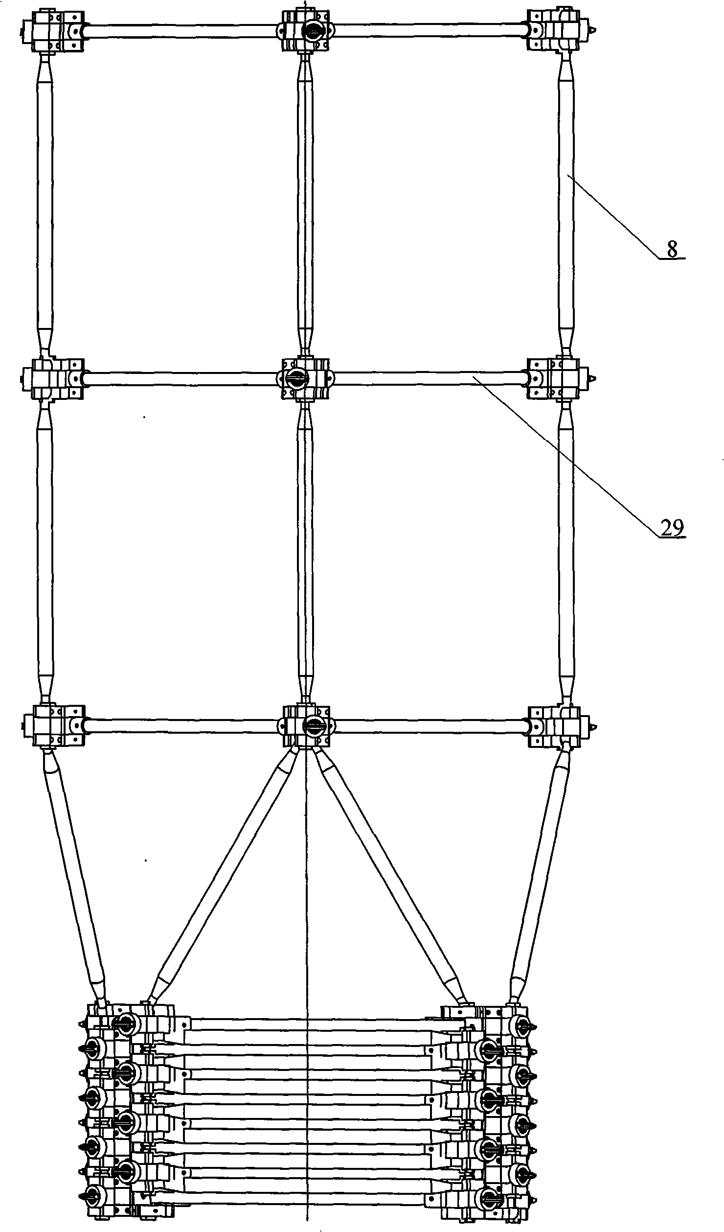
[0009] Specific implementation mode three: combination figure 2 , Figure 6 Illustrate this embodiment, the cable rod type extension arm 18 of this embodiment is made up of lower corner block 25, four middle corner blocks 26, upper corner block 27, ball hinge 28, four cross bars 29, four connecting rods 8; A cross bar 29 is rigidly connected with four middle corner blocks 26 to form a square rigid plane, and the middle corner block 26 is fixedly connected with the upper corner block 27 and the lower corner block 25 to form two ball sockets. The four connecting rods 8 are vertically arranged on Between two adjacent square rigid planes and located at the four corners of the square rigid planes, both ends of each connecting rod 8 are respectively hinged with the ball sockets corresponding to the two adjacent square rigid planes. Such arrangement has the advantages of simple structure and reliable operation. Other components and connections are the same as those in the first em...


PUM


Abstract

A space deployment and drive mechanism of a large-sized rod-cable type deployable arm is provided by the invention, and the mechanism relates to the space deployment and drive mechanism of the rod-cable type deployable arm. The space deployment and drive mechanism of the invention can solve the problems that the existing large-sized rod-cable type deployable arm adopts a four-thread screw lift telescopic mechanism for driving, thus requiring high manufacturing accuracy and manufacturing process and causing that the deployable arm is easy to be blocked. A bottom end cover (1), a furl sleeve (2), a racemization sleeve (3) and a drive sleeve (4) are fixedly connected together. The inner wall of the racemization sleeve (3) is provided with an eight-curve groove (15) and the inner wall of the furl sleeve (2) is fixedly provided with eight rectilinear orbits (9). A drive sprocket (10) and a driven sprocket (13) which are driven by chains (11) are fixedly connected with the drive sleeve (4). Three chain tooth slices (12) are equally spaced and arranged on each chain. Each vertex angle of the rod-cable type deployable arm component is fixedly provided with a roller wheel (6) which is embedded with a deployable arm tooth slice (5). The chain tooth slice (12) is meshed with the deployable arm tooth slice (5) and the drive sprocket (10) is connected by a reverse driving mechanism. The space deployment and drive mechanism of the invention has the advantage of the strong acceptance capacity of the deformation of the deployable arm and mismachining tolerance.

Description

technical field [0001] The invention relates to a space cable-rod type extension arm deployment driving mechanism. Background technique [0002] The space cable rod type extension arm has the characteristics of high retraction rate, high rigidity, high deployment positioning accuracy, high reliability, good mechanical and thermal stability, repeatable deployment and retraction, and theoretically unlimited length deployment. At present, the space cable-rod extension arm has been widely used. Its main function is to deploy flexible solar panels; support extendable antennas, synthetic aperture radars, and space telescopes; In order to reduce mutual interference and so on. The driving mechanism of the space cable-rod extension arm determines whether it can be normally deployed and retracted in the space environment to ensure its normal operation. In addition, factors such as the complexity and quality of the driving mechanism, structural size, reliability, and cost directly re...

Claims


Application Information

Patent Timeline
Patent Type & Authority Applications(China)
IPC IPC(8): B64G1/22
Inventor 刘荣强邓宗全郭宏伟罗阿妮罗昌杰
Owner BEIJING INST OF SPACECRAFT SYST ENG
Learn More