Straight-through current transformer for measuring voltage by penetrating wire wrapper
A current transformer and core-through technology, which is applied in the field of transformers, can solve the problems of easy electricity theft and low efficiency, and achieve the effects of avoiding electricity theft, simple use, convenient use and management
- Summary
- Abstract
- Description
- Claims
- Application Information
AI Technical Summary
Problems solved by technology
Method used
Image
Examples
Embodiment 1
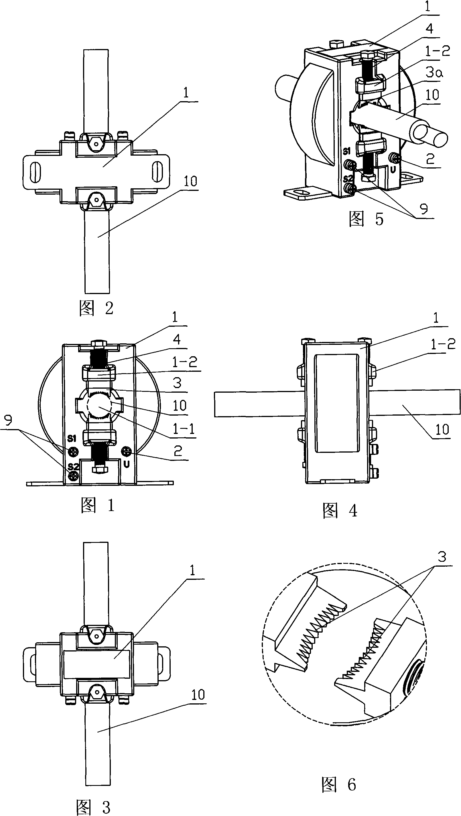
[0040] A core-through current transformer that utilizes a puncture method to obtain voltage from the sheathed wire, referring to Figures 1 to 5, it includes a transformer body 1 with a core-through hole 1-1, and the transformer body 1 is respectively provided with The voltage line terminal 2 and the voltage-taking component 3 are electrically connected, and this connection includes any electrical connection in the prior art. The voltage taking part 3 in this embodiment has a sharp front end, and the transformer of this structure can be applied on the wire 10 covered with insulation, and the front end of the spike can pierce the insulation skin of the wire 10, so that the voltage taking The component 3 is electrically connected with the metal wire in the insulating skin so as to realize the extraction of the voltage signal of the wire.
[0041] Specifically, the spiked front end of the voltage-taking component is a group of front ends with needle-like or saw-tooth structures. I...
Embodiment 2
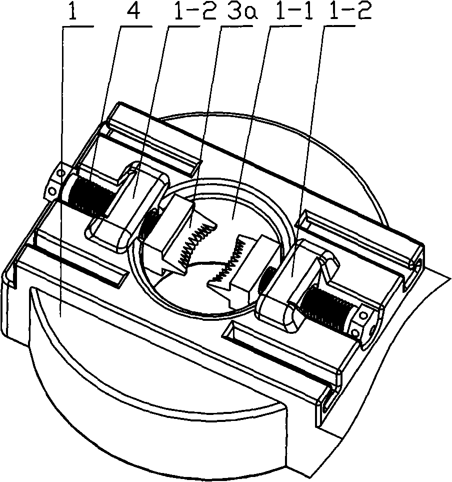
[0048] For the situation where the voltage is taken by the metal stud 4 as a conductor, a more preferred structure is to fix the metal insert 1-2 on the transformer body 1, and the metal insert 1-2 is connected to the voltage line terminal 2 Electrical connection; the metal stud 4 is threadedly connected with the metal insert 1-2, and the metal stud 4 can move radially along the through hole.
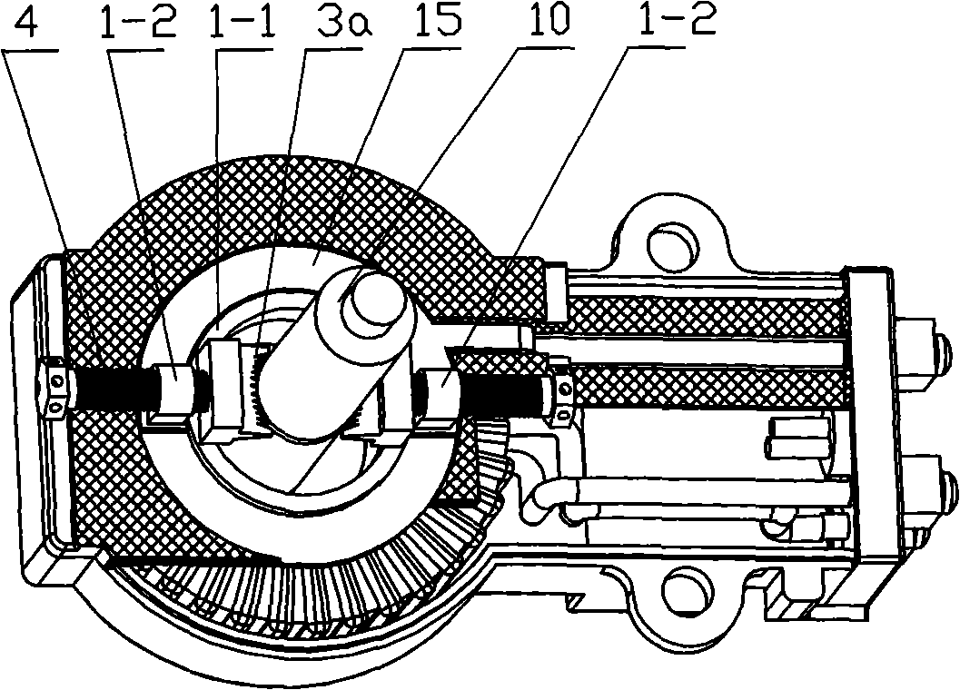
[0049] A more preferred structure is that on the transformer body 1, two metal inserts 1-2 are set around the through-hole 1-1, refer to Figure 7 , all metal inserts 1-2 are electrically connected through conductor 15, refer to Figure 8 , the conductor 15 in this embodiment is a metal sheet, of course, wires can also be used for electrical connection. All metal inserts 1-2 are threadedly connected with metal studs 4, like this, the voltage-taking parts in two directions simultaneously pierce the tip into the busbar, making the electrical connection more stable and accurate, thereby be...
Embodiment 3
[0054] The difference from the existing structure is that the No. 1 anti-stealing mask 5 described in this embodiment is connected to the surface of the transformer body 1 in a non-detachable manner. It can be seen that the anti-stealing mask defined in this embodiment is fixed. On the body of the transformer, in this way, the transformer can be used in any position and not limited to the box. The mask is connected to the transformer body in a non-detachable way, that is to say, after the metering department fixes the anti-stealing mask to the transformer, the mask cannot be removed from the transformer without destroying it. Those who can't hide the eyes and ears to steal electricity can greatly increase the degree of protection against electricity theft.
[0055] refer to Figure 9 to Figure 11 , this non-detachable connection structure is that the No. 1 anti-stealing mask 5 located on one side of the transformer is a whole, and the No. 1 anti-stealing mask 5 is provided wi...
PUM
 Abstract
Description
Claims
Application Information
 - R&D Engineer
- R&D Manager
- IP Professional
- Industry Leading Data Capabilities
- Powerful AI technology
- Patent DNA Extraction
Browse by: Latest US Patents, China's latest patents, Technical Efficacy Thesaurus, Application Domain, Technology Topic, Popular Technical Reports.
© 2024 PatSnap. All rights reserved.Legal|Privacy policy|Modern Slavery Act Transparency Statement|Sitemap|About US| Contact US: help@patsnap.com


