


Quick Research
Generate reliable direction feasibility study reports for your R&D in just a few steps.

Technical Q&A
Discover and master advanced knowledge NOW. Basics, ideas, possibilities, all at once.

Find Solutions
As an expert in R&D theories, this can generate solutions to your technical problems instantly.

Evaluate Feasibility
Analyze your overall solution with one click, know your potential R&D risks in advance.

Monitor Landscape
Get weekly tech updates, stay abreast of the latest tech innovations and key insights.
Combination bench saw head overturn structure
A technology of flipping structure and machine head, which is applied in the field of composite table data, can solve the problems of high manufacturing cost of composite table data, and achieve the effects of saving raw material resources, reducing thickness, and reducing manufacturing costs
- Summary
- Abstract
- Description
- Claims
- Application Information
AI Technical Summary
Problems solved by technology
Method used
Image

Examples
Embodiment 1
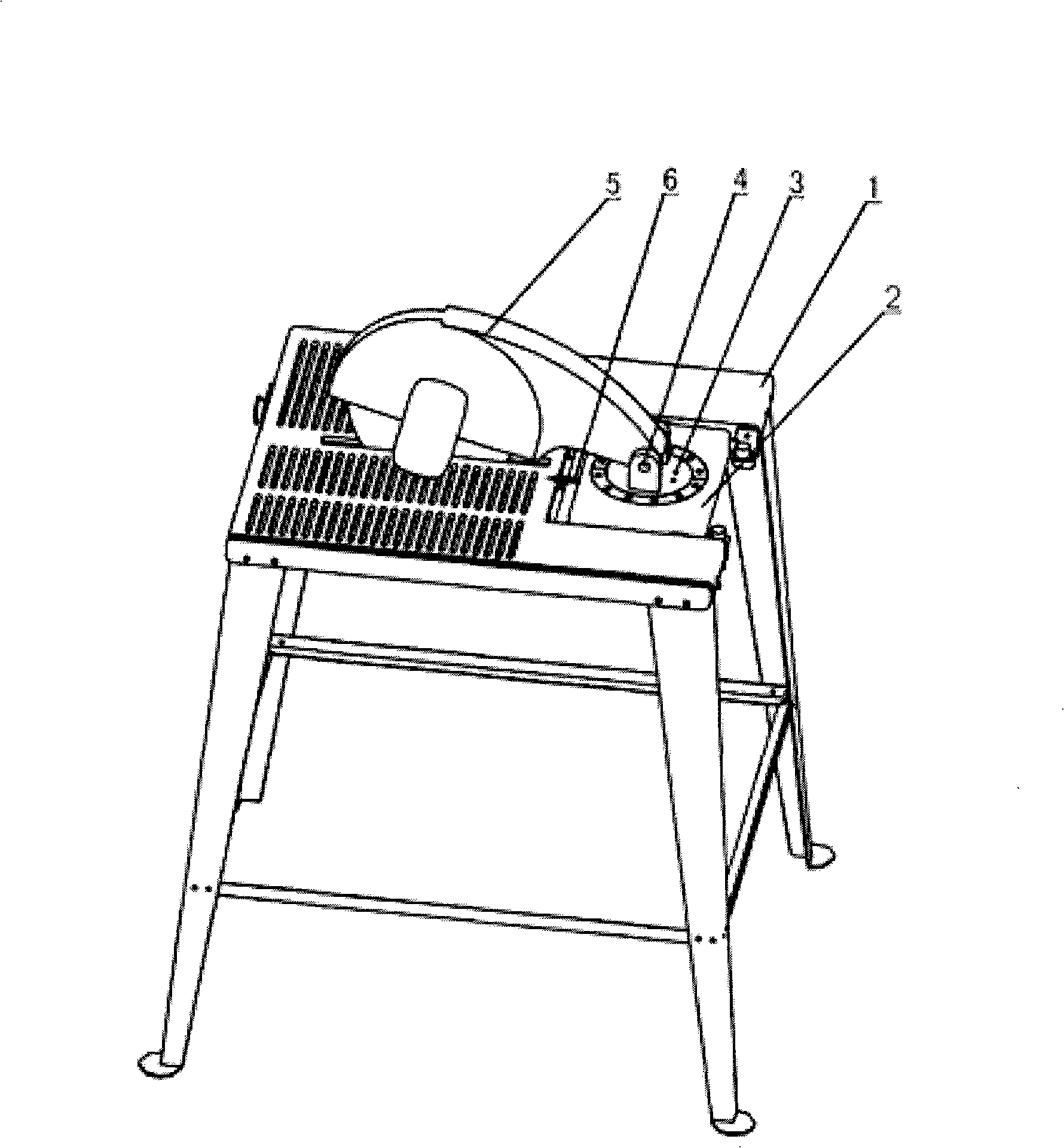
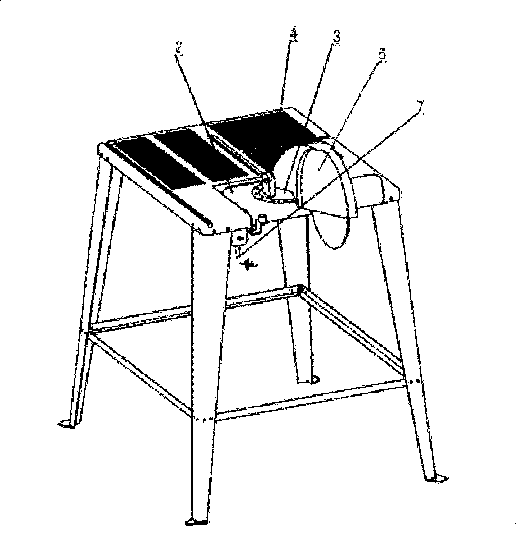
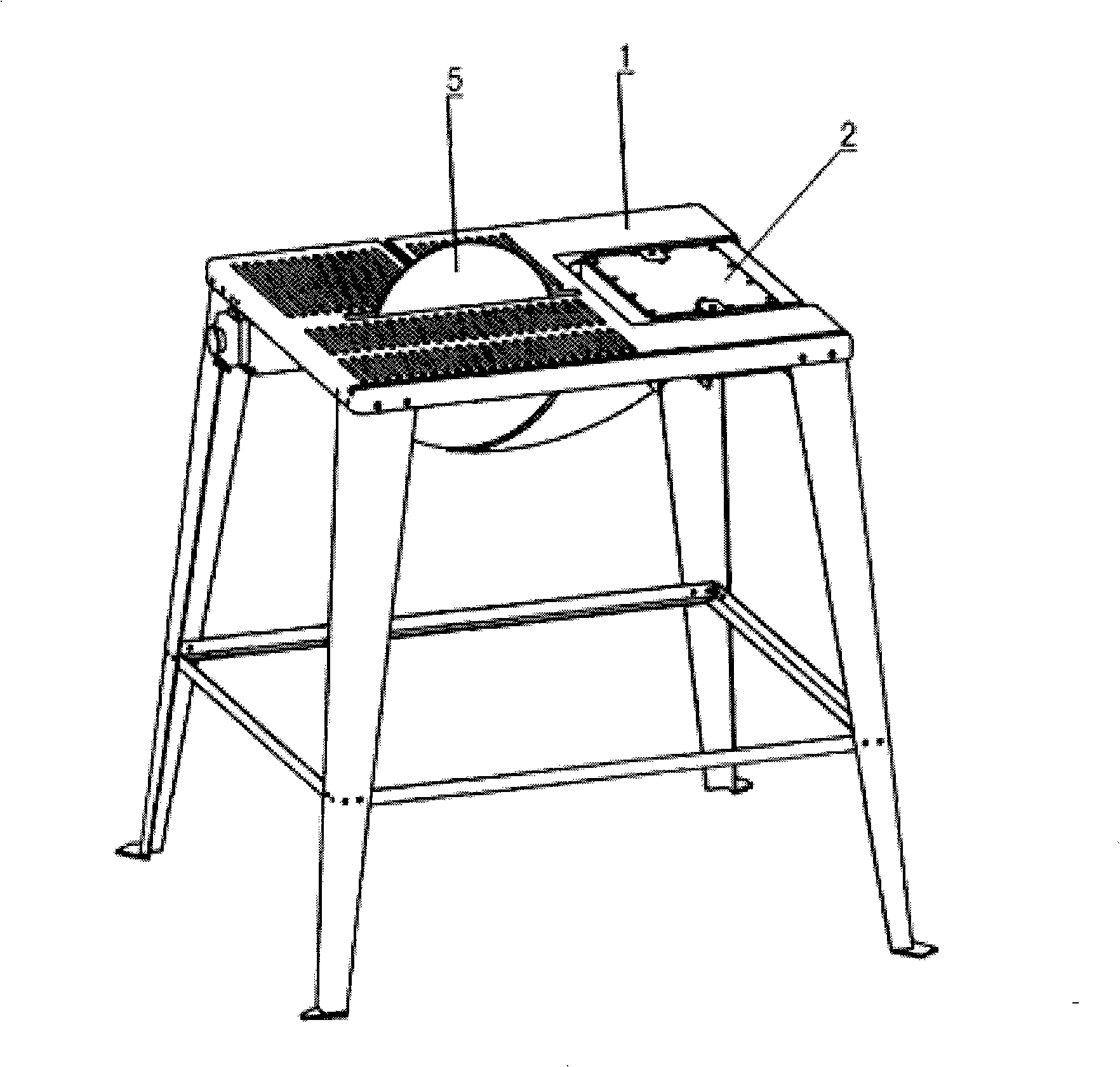
[0034] Refer to attached Figure 1-8 , 11:
[0035] The turning structure of the composite table saw head according to the present invention includes a turning table 2 and a swivel seat 3 arranged on the turning table 2, and the rotating seat 3 is equipped with a mounting seat 5 for installing the head of the compound table saw. The table 2 is connected to the work table 1 through a rotating shaft parallel to the work table 1, and there is a device between the turning table 2 and the work table 1 so that the turning table is positioned at the position where the front faces the work table 1, or the reverse side faces the work table 1. The first positioning mechanism, the swivel base 3 is connected on the turning platform 2 in a manner that can rotate in the plane of the turning platform 2, and the second positioning mechanism is installed between the turning base 3 and the turning platform 2.
[0036] Said first positioning mechanism includes a positioning pin 9 extending out ...
Embodiment 2
[0046] Refer to attached Figure 1-8 , 12:
[0047] On the basis of the first embodiment, the change made in this embodiment is the setting method of the second positioning mechanism.
[0048] The second positioning mechanism used in this embodiment includes setting a bolt 19b identical to the bolt 19a on the swivel base 3, and the latch 19b and the latch 19a are symmetrical to the rotation center of the swivel base 3, and a torsion spring 27 is installed. In this way, as long as the first insertion hole 25 is provided on the turning table 2 , when the machine head needs to be rotated by 180 degrees, the latch 19 b is positioned in the first insertion hole 25 .
[0049] All the other are identical with embodiment.
Embodiment 3
[0051] Refer to attached Figure 1-8 , 10:
[0052] On the basis of the first embodiment, the change of this embodiment is the setting method of the second positioning mechanism.
[0053] The second positioning mechanism adopted in this embodiment includes a latch 19 arranged on the turning table 2 and a first insertion hole 26 and a second insertion hole 26a arranged on the swivel base 3 and cooperating with the latch 19. The first insertion hole 26 has the function of positioning the swivel seat 3 so that the machine head faces the position suitable for the state of the table saw, and the second insertion hole 26a has the function of positioning the swivel seat 3 so that the machine head faces the position suitable for the state of the cutting saw. Location.
[0054] All the other are the same as the first embodiment.
PUM
 Abstract
Description
Claims
Application Information
 - R&D Engineer
- R&D Manager
- IP Professional
- Industry Leading Data Capabilities
- Powerful AI technology
- Patent DNA Extraction
Browse by: Latest US Patents, China's latest patents, Technical Efficacy Thesaurus, Application Domain, Technology Topic, Popular Technical Reports.
© 2024 PatSnap. All rights reserved.Legal|Privacy policy|Modern Slavery Act Transparency Statement|Sitemap|About US| Contact US: help@patsnap.com