
Modified type polishing pad regulating apparatus technique

A polishing pad and regulator technology, which is applied in the direction of surface polishing machine tools, grinding/polishing equipment, manufacturing tools, etc., can solve the problems of shortening the service life of the polishing pad and the surface wear of the polishing pad, so as to avoid micro-scratches and prolong the life of the polishing pad. The effect of service life and reduction of wear rate

Inactive Publication Date: 2011-03-23
SEMICON MFG INT (SHANGHAI) CORP
View PDF6 Cites 0 Cited by
  • Summary
  • Abstract
  • Description
  • Claims
  • Application Information

AI Technical Summary

Problems solved by technology

The continuous high-pressure action will not only dress and clean the surface of the polishing pad, but also cause a large degree of wear on the surface of the polishing pad, shortening the service life of the polishing pad

Method used


Image

  • Modified type polishing pad regulating apparatus technique
  • Modified type polishing pad regulating apparatus technique

Examples


Embodiment Construction

[0016] The improved pad conditioner process of the present invention will be described in further detail below.

[0017] The improved polishing pad conditioner technique of the present invention firstly adopts high pressure (high down force) to wash and repair the polishing pad surface, to remove the polishing liquid crystallized matter remaining in the groove of the polishing pad surface, prevent the groove from clogging and make the polishing pad flat , can also prevent micro-scratches on the wafer surface during polishing. In this step, the initial position of the polishing pad adjuster can be set at a position of 1.4 to 1.6 inches from the center of the polishing pad, so that the working range of the polishing pad adjuster can be expanded to better remove the polishing pad center area. liquid crystal, and ensure that it does not collide with the polishing head during the movement. Preferably, the distance may be set at 1.4 inches.

[0018] After the high pressure flushin...


PUM


Abstract

The invention provides an improved process for polishing pad regulator, which relates to a chemical mechanical polishing process. By adopting the existing process for polishing pad regulator, the crystals of polishing slurry on the surface of the polishing pad can be effectively removed and the service life of the polishing pad is shorter. In the improved process for polishing pad regulator of the invention, the surface of the polishing pad is first washed and dressed adopting high-pressure water or the polishing slurry so as to remove the crystals of the polishing slurry, and then a main polishing procedure is carried out on the condition of low pressure. In the steps of high-pressure washing and dressing, the distance from the initial position of the polishing pad regulator to the center of the polishing pad ranges from 1.4 to 1.6 inches. By adopting the process for polishing pad regulator of the invention, polishing slurry residues left in the grooves of the polishing pad can be reduced, tiny abrasion on the circular surface of the crystal caused in the process of process can be avoided, and moreover the service life of the polishing pad can be greatly prolonged.

Description

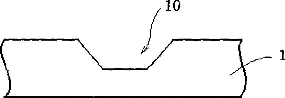
technical field [0001] The invention relates to a chemical mechanical polishing process, in particular to a polishing pad conditioner process. Background technique [0002] Chemical Mechanical Polishing (CMP) is an important process in the manufacturing process of integrated circuits, mainly used for planarization and wafer cleaning of the wafer surface. [0003] like figure 1 Shown, the surface of the polishing pad (pad) 1 used in the chemical mechanical polishing process has many grooves 10, if the polishing liquid (slurry) remaining in the groove 10 and the by-product of the polishing process are not removed in time, the polishing liquid After drying, polishing liquid crystals will be formed in the grooves 10, and after a long time, the grooves 10 on the surface of the polishing pad 1 will be filled to make the polishing pad 1 flat. Using such a polishing pad for wafer polishing will not only affect the effect of the polishing process, but also cause micro-scratches on ...

Claims


Application Information

Patent Timeline
Patent Type & Authority Patents(China)
IPC IPC(8): B24B29/00B24B57/02
Inventor 王莉赵铁军
Owner SEMICON MFG INT (SHANGHAI) CORP
Learn More