Charge control apparatus, electrically powered vehicle and electric storage charge control method

一种充电控制、蓄电装置的技术,应用在电动力装置、电池电路装置、动力装置等方向,能够解决单相电源限制等问题,达到开关损耗最小化、成本缩减的效果

Inactive Publication Date: 2008-10-01
TOYOTA JIDOSHA KK
View PDF1 Cites 13 Cited by
  • Summary
  • Abstract
  • Description
  • Claims
  • Application Information

AI Technical Summary

Problems solved by technology

[0005] However, in order to achieve controlled battery charging with a power factor of 1 in this motor drive and power processing device, the single-phase power available to charge the battery is limited

Method used


Image

  • Charge control apparatus, electrically powered vehicle and electric storage charge control method
  • Charge control apparatus, electrically powered vehicle and electric storage charge control method
  • Charge control apparatus, electrically powered vehicle and electric storage charge control method

Examples


Embodiment Construction

[0034] Embodiments of the present invention will be described in detail below with reference to the accompanying drawings. Throughout the drawings, the same or corresponding parts are denoted by the same reference numerals, and their descriptions will not be repeated.

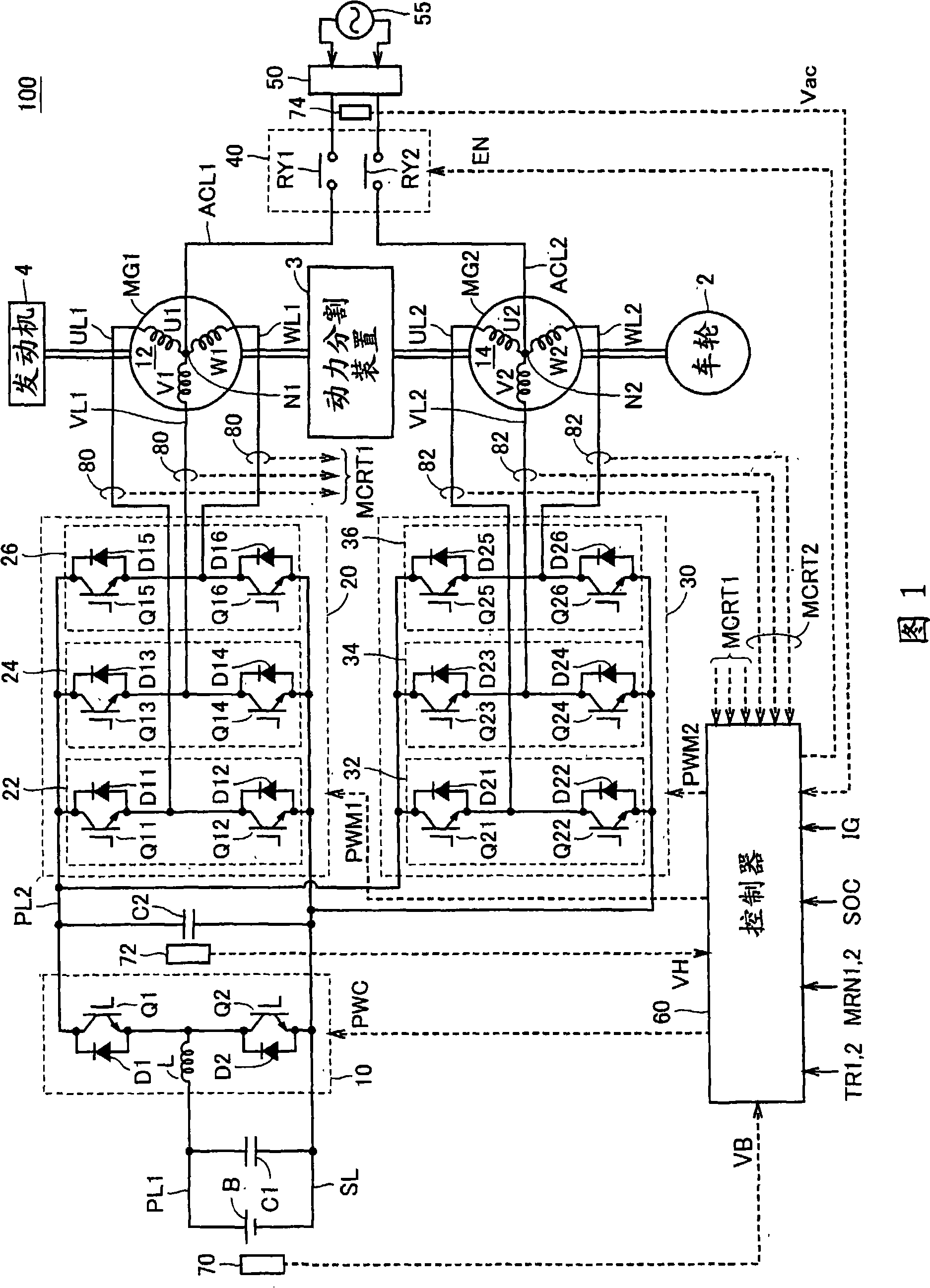
[0035] FIG. 1 is an overall block diagram of a hybrid vehicle shown as an example of an electric vehicle according to an embodiment of the present invention. Referring to FIG. 1 , a hybrid vehicle 100 includes an engine 4 , motor generators MG1 and MG2 , a power split device 3 , and wheels 2 . Hybrid vehicle 100 also includes power storage device B, boost converter 10, converters 20 and 30, controller 60, capacitors C1 and C2, power lines PL1 and PL2, ground line SL, U-phase lines UL1 and UL2, V-phase Lines VL1 and VL2 , W-phase lines WL1 and WL2 , voltage sensors 70 and 72 , and current sensors 80 and 82 . The hybrid vehicle 100 further includes electric power input lines ACL1 and ACL2 , a relay circuit 40 ,...


PUM


Abstract

When it is determined that an electric storage (B) is to be charged from a commercial power source (55), a controller (60) sets a control target of a voltage VH of a power line (PL2) to be controlled by a boost converter (10), based on a voltage Vac of the commercial power source (55). Specifically, the controller (60) sets the control target of the voltage VH to a level approximately equal to the crest value of voltage Vac. Then, the controller (60) outputs an input permission command (EN) to a relay circuit (40), and controls inverters (20, 30) to execute charging of the electric storage (B).

Description

technical field [0001] The invention relates to a charge control device and an electric vehicle. Specifically, the present invention relates to charge control of a power storage device mounted on an electric vehicle such as an electric vehicle or a hybrid vehicle. Background technique [0002] Japanese Patent Laid-Open No. 04-295202 discloses a motor drive and power processing device used in electric vehicles. This motor drive and power processing device includes a secondary battery, inverters IA and IB, induction motors MA and MB, and a control unit. The induction motors MA and MB respectively comprise Y-connected windings CA and CB, and input / output ports are connected to neutral points NA and NB of the windings CA and CB through EMI filters. [0003] Inverters IA and IB are provided corresponding to induction motors MA and MB, respectively, and are connected to windings CA and CB, respectively. Inverters IA and IB are connected in parallel to the secondary battery. ...

Claims


Application Information

Patent Timeline
Patent Type & Authority Applications(China)
IPC IPC(8): B60L11/18H02J7/00
CPCB60L11/1811B60L11/1803B60L2210/20Y02T10/6239Y02T10/6269Y02T10/7225Y02T90/14H02J7/022B60K6/365Y02T90/127Y02T10/7088Y02T10/7005Y02T10/725B60K1/02B60K6/445B60L2210/14Y02T10/92Y02T10/7072B60L50/51B60L53/20H02J7/02H02J2207/20Y02T10/62Y02T10/72Y02T10/70B60Y2200/91B60Y2200/92Y02T90/12
Inventor 及部七郎斋中村诚石川哲浩吉田宽史
Owner TOYOTA JIDOSHA KK
Why Eureka
Try Eureka