Cutting knife

A technology of cutting knives and blades, which is applied in metal processing and other directions, can solve the problem of blade falling off, achieve the effect of improving safety and easy replacement operations

Active Publication Date: 2008-09-24
KOKUYO CO LTD
View PDF1 Cites 2 Cited by
  • Summary
  • Abstract
  • Description
  • Claims
  • Application Information

AI Technical Summary

Problems solved by technology

[0005] However, the structure of the cutting knife disclosed in Patent Document 1 is such that the blade is only hung on the slider, and there is a possibility that the blade may be removed from the slider when the blade is taken out together with the slider from the knife housing for replacement or the like. Unpredictably come off such a disadvantage

Method used


Image

  • Cutting knife
  • Cutting knife
  • Cutting knife

Examples


Embodiment Construction

[0046] Hereinafter, embodiments of the present invention will be described in detail with reference to the drawings. In addition, in this specification, so-called 'front' means the side where the tip of the blade is located, and 'rear' means the opposite side.

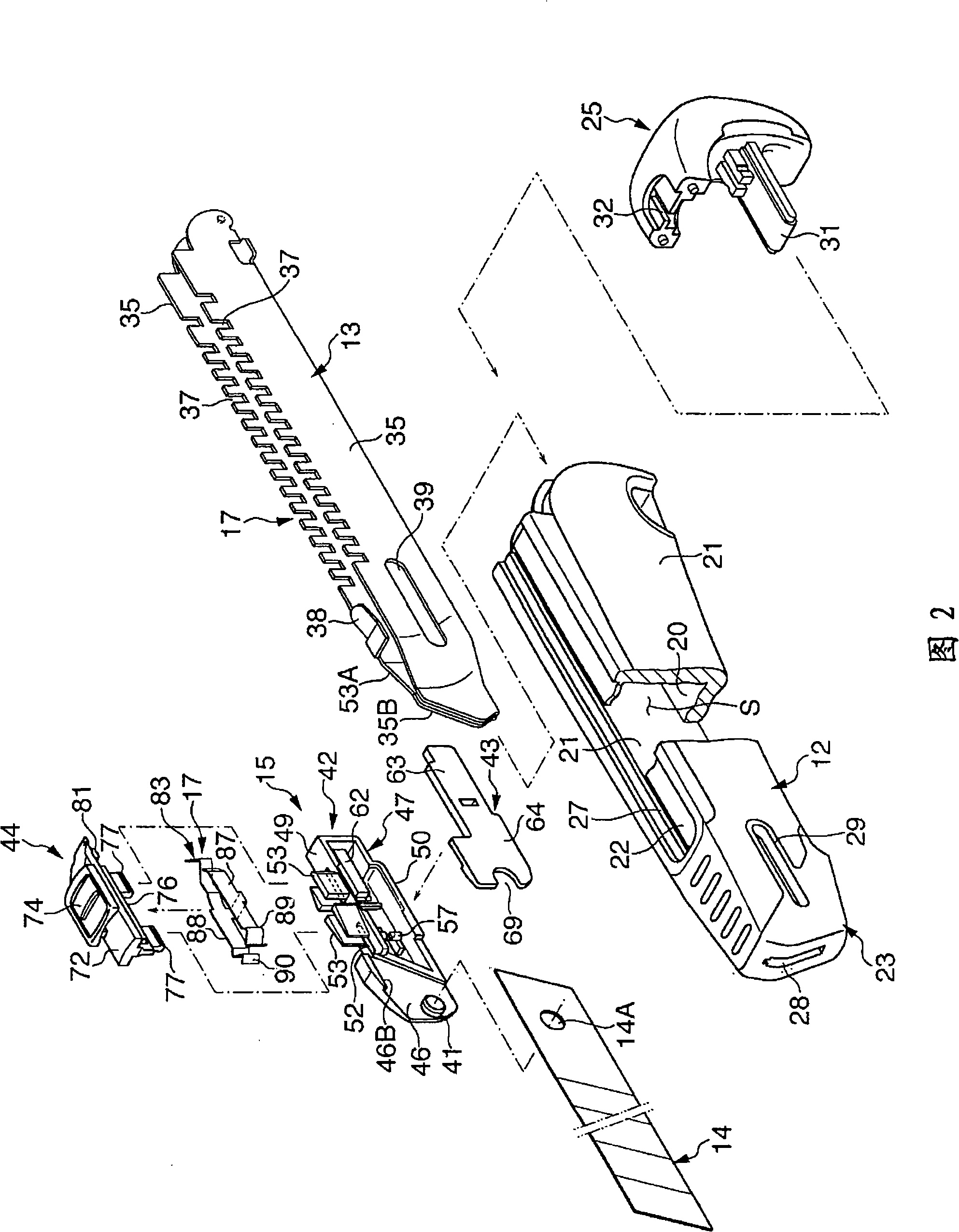
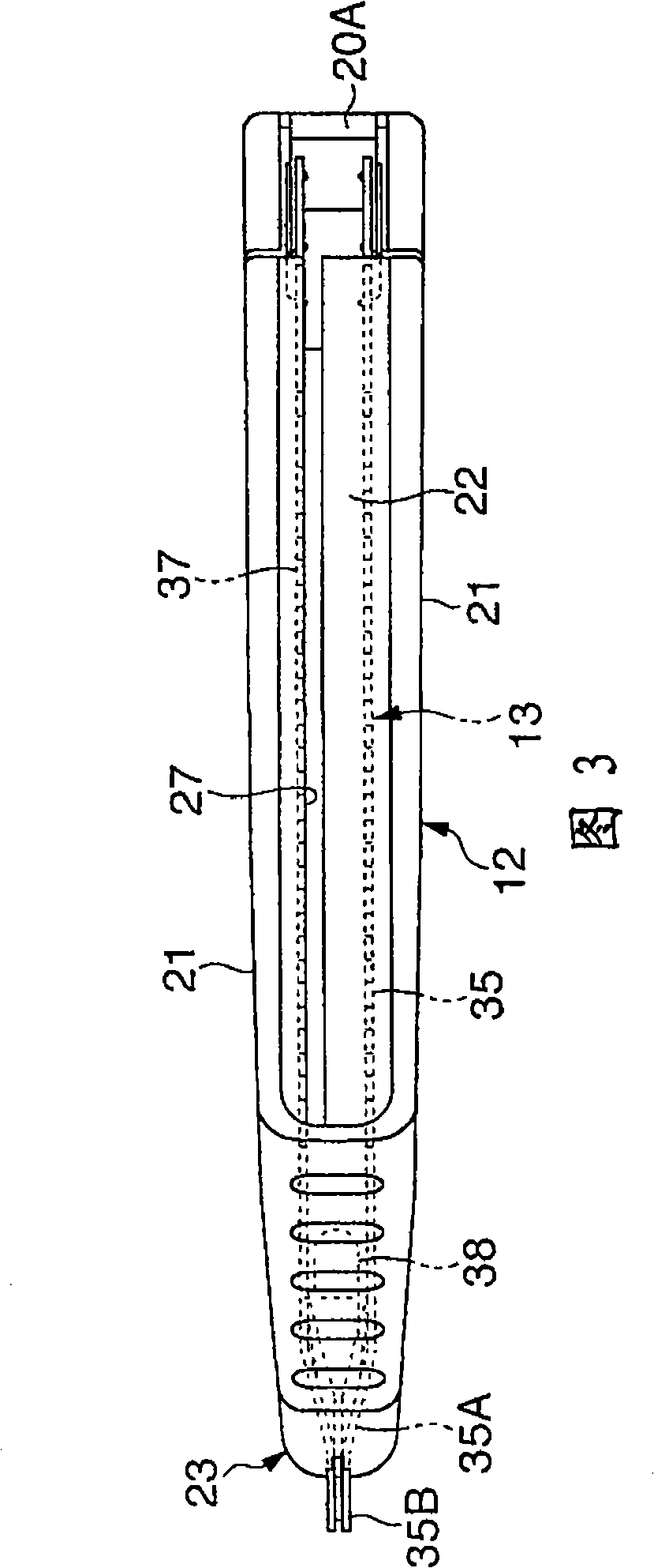
[0047] FIG. 1 is a schematic perspective view of a cutting blade according to this embodiment, and FIG. 2 is an exploded perspective view thereof. In these figures, the cutting knife 10 is configured to include: a knife case 12 having an inner space S extending in the front-rear direction; a guide member 13 housed in the knife case 12; 13 moves in the front-rear direction so as to be able to come in and out of the blade 14 from the front end of the knife housing 12; hold the blade 14 and be set to a slider 15 that can move along the guide member 13 together with the blade 14; Between the device 15 and the knife housing 12, the locking mechanism 17 that simultaneously restricts the forward and backward movement of the ...


PUM


Abstract

The invention provides a cutting-off knife whose knife blade do not fall of from a sliding device surprisingly at the time of replacement for the knife blade. The cutting-off knife (10) includes: a knife shell (12) extending in front and rear directions, the knife blade (14) contained within the knife shell, the sliding device (15) holding the knife blade (14) to move in the front and rear directions. The sliding device (15) comprises: a sliding device main body (42) which can be located in a hole (14A) of the knife blade (14) and takes a projection 41 as a temporary holding part, and a pressing component (43) which can be joltily connected to the sliding device main body (42); and rear part of the knife blade (14) is clamped between the sliding device main body (42) and the pressing component (43).

Description

technical field [0001] The present invention relates to a cutting blade, and more specifically, relates to a cutting blade having a structure in which the blade does not come off unexpectedly when the blade is replaced. Background technique [0002] A well-known cutting knife is composed of: a substantially C-shaped knife case extending in the front-rear direction; a slider provided to be movable in the front-back direction in the knife case; blade. A locking mechanism is installed between the slider and the blade, by means of the locking mechanism, the blade can protrude from the top of the knife case in stages, and on the other hand, the blade can also be kept in a certain position. [0003] This type of cutting blade is, for example, as described in Patent Document 1, a protrusion is formed on the above-mentioned slider, and a hole is formed in the rear end surface of the blade, and the protrusion is positioned in the hole, by This enables the linkage between the slider...

Claims


Application Information

Patent Timeline
Patent Type & Authority Applications(China)
IPC IPC(8): B26B1/08B26B5/00
Inventor 篠原胜
Owner KOKUYO CO LTD
Why Eureka
Try Eureka