
Method for measuring temperature of distributed optical fiber temperature transducer system

A temperature sensor, distributed optical fiber technology, applied in the direction of physical/chemical changes in thermometers, thermometers, measuring devices, etc., can solve the problems of removal, large error in optical fiber temperature value, circuit and environmental noise, and large nonlinear effects. , to ensure the accuracy

Active Publication Date: 2008-09-03
浙江振东光电科技有限公司
View PDF0 Cites 13 Cited by
  • Summary
  • Abstract
  • Description
  • Claims
  • Application Information

AI Technical Summary

Problems solved by technology

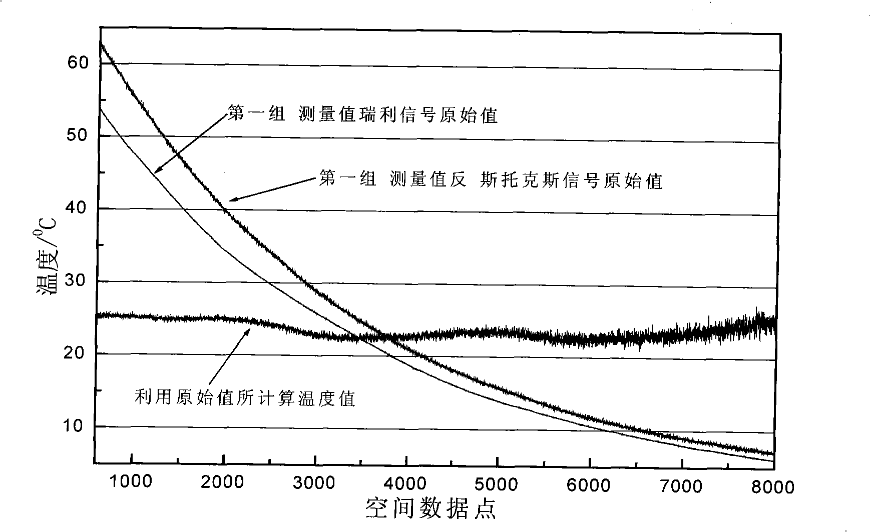
[0017] In the actual distributed optical fiber temperature sensor system, because the reflected optical signal is very weak, the noise and nonlinearity of the circuit and the environment have a great influence, and cannot be removed by conventional methods such as accumulation and averaging. The actual measurement of the Rayleigh scattering signal and pull There is a large error in the level of the Mann scattering signal, so the error of the temperature value of each point on the optical fiber calculated by formula (6) is also large, and the temperature value is not accurate enough

Method used


Image

  • Method for measuring temperature of distributed optical fiber temperature transducer system
  • Method for measuring temperature of distributed optical fiber temperature transducer system
  • Method for measuring temperature of distributed optical fiber temperature transducer system

Examples


Embodiment Construction

[0036] The present invention will be further described in detail below in conjunction with the accompanying drawings and embodiments.

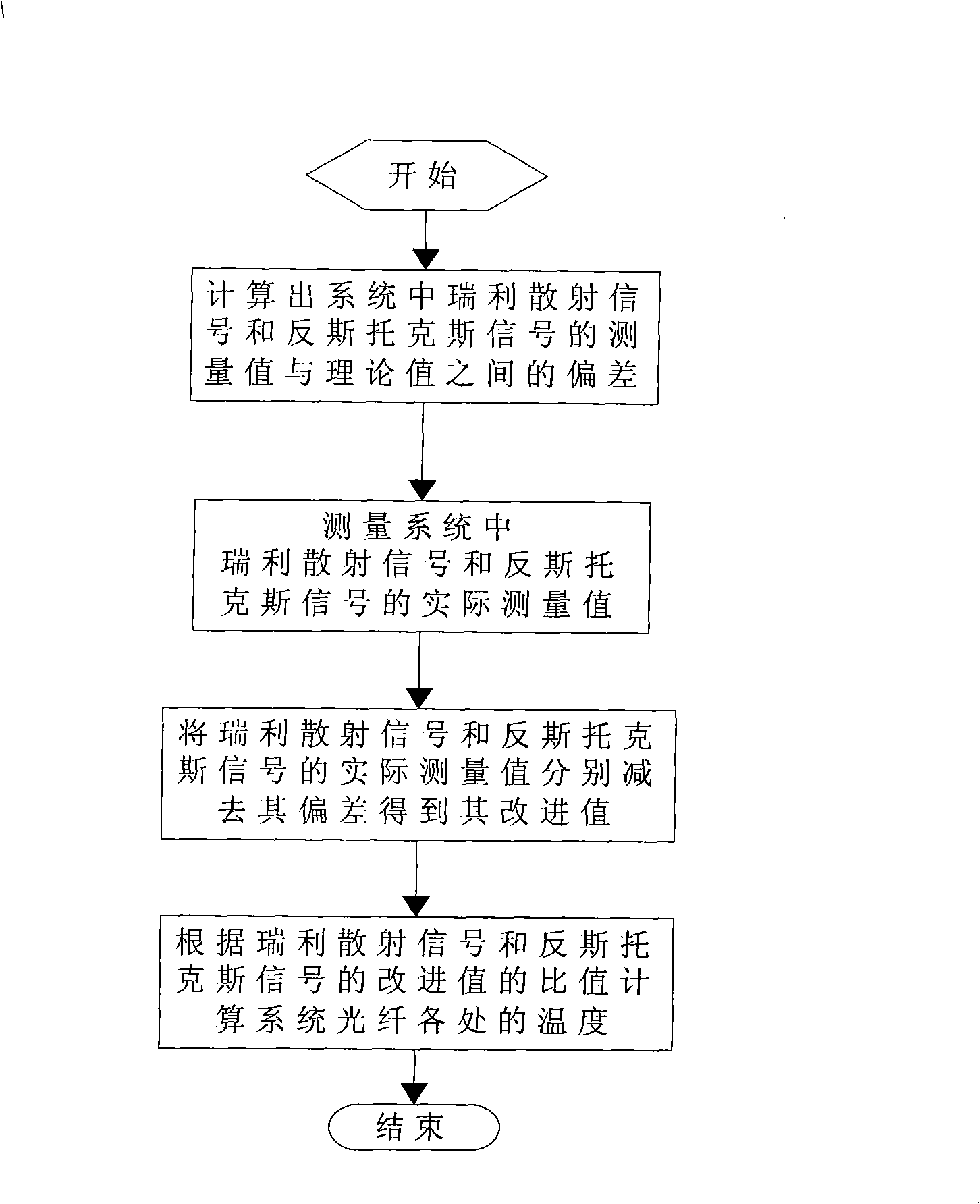
[0037] Such as figure 1 , the invention provides a temperature measurement method of a distributed optical fiber temperature sensor system, which comprises the following steps:

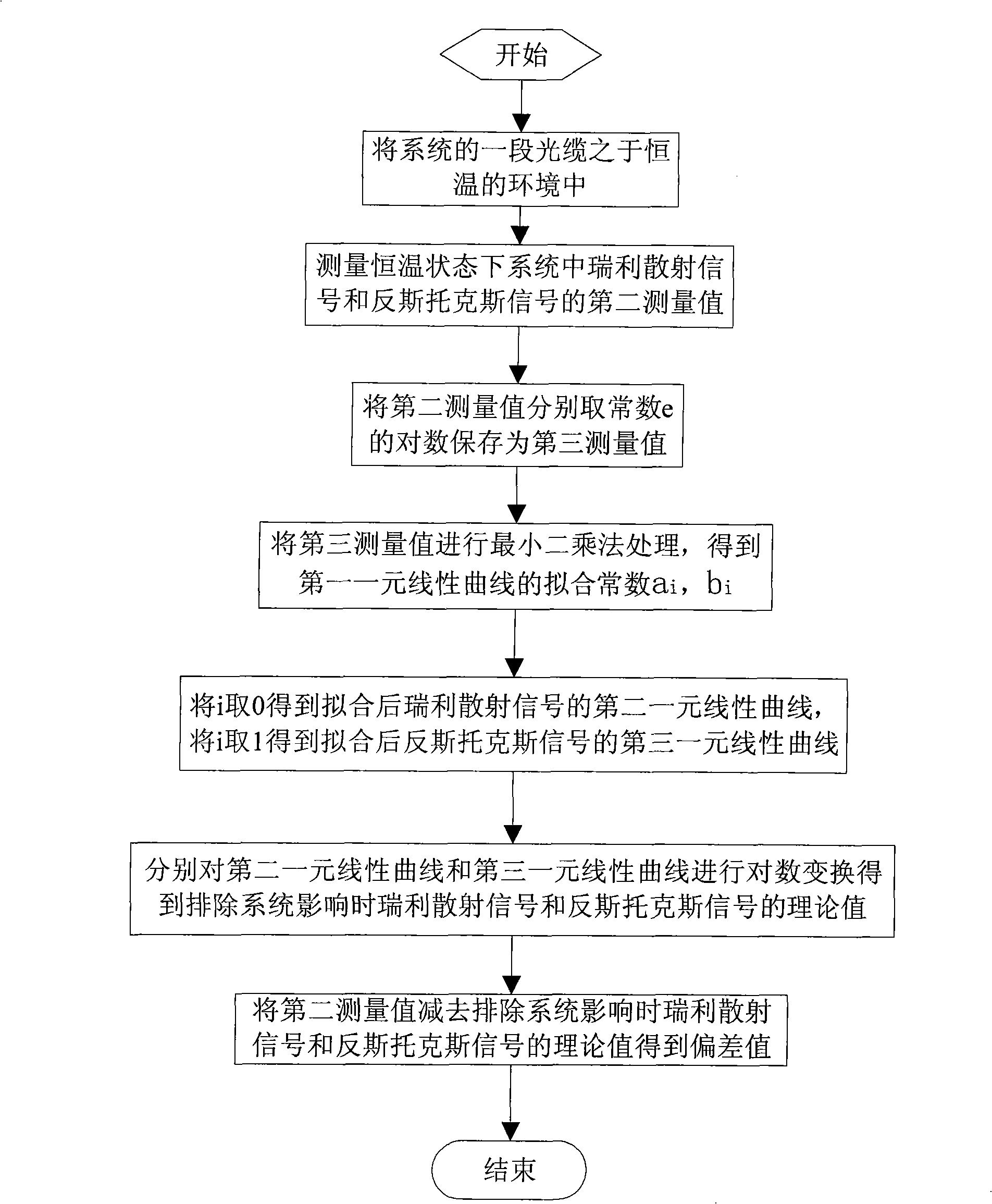
[0038] (1), first calculate the deviation σ between the measured value of the Rayleigh scattering signal in the distributed optical fiber temperature sensor system and the theoretical value of the Rayleigh scattering signal after excluding the influence of the system r , and the deviation σ between the measured value of the anti-Stokes signal in the distributed optical fiber temperature sensor system and the theoretical value of the anti-Stokes signal after excluding the influence of the system a , and use this deviation as an inherent characteristic of the distributed optical fiber temperature sensor system;

[0039] (2), respectively measuring the first group of m...


PUM


Abstract

The invention relates to a method for measuring temperature of the distributed optical fiber sensor system, which includes the following steps: (1) calculating the deviations between the measured values and the theoretical values of Rayleigh scattering signal and antistokes signal in system, (2) obtaining the improved values by subtracting the deviations from the measured values of actual Rayleigh scattering signal and antistokes signal in system, (3) determining the temperature value of every point on the optical fiber according to the ration between the improved values of the Rayleigh scattering signal and the anti-Stokes signal. Compared with the prior art, the invention has the advantages that: the result is calculated by the deviation between the measured values of the circuit and ambient noise, and the nonlinear pair Rayleigh scattering signal and the antistokes signals in the specific distributed optical fiber temperature sensor system and the theoretical values excluding the influence of the system, the measured value is compensated, which ensures the accuracy of sample in the Rayleigh scattering signal and the antistokes signal, and further ensures the accuracy of the collected temperature in the distributed optical fiber temperature sensor system.

Description

technical field [0001] The invention relates to a temperature measurement method of a distributed optical fiber temperature sensor system. Background technique [0002] Temperature is one of the important state parameters of all physical, chemical and biological processes, and temperature measurement plays a very important role in engineering applications and scientific research. Because the optical fiber itself is not affected by radio frequency fields and other electromagnetic radiation interference, does not generate electric sparks, and has good insulation properties, the optical fiber temperature sensor has become an effective means of measuring distributed temperature in military and civilian structures. [0003] Distributed optical fiber temperature sensing system is a sensing system for real-time measurement of spatial temperature field distribution. This technology was first proposed by the University of Southampton in England in 1981, and products have been develo...

Claims


Application Information

Patent Timeline
IPC IPC(8): G01K11/32G01K11/324
Inventor 杨如祥鲁展赵飞
Owner 浙江振东光电科技有限公司
Learn More