
Take-up winder with protecting cover

A technology for a protective cover and a wire drawing machine, which is applied in the field of wire drawing machines, can solve problems such as fire hazards and easy wire breakage, and achieve the effect of reducing the possibility of fire and not easily breaking wires

Inactive Publication Date: 2008-09-03
周贤言
View PDF0 Cites 2 Cited by
  • Summary
  • Abstract
  • Description
  • Claims
  • Application Information

AI Technical Summary

Problems solved by technology

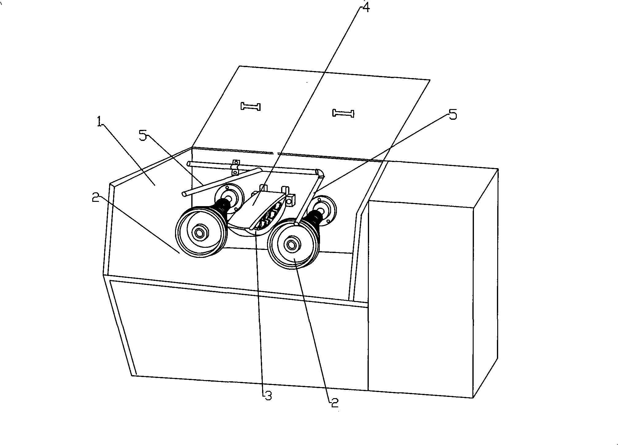
[0003] In order to solve the shortcomings of the traditional wire drawing machine that is easy to break wires and have fire hazards, the present invention proposes a wire drawing machine with a protective cover that is not easy to break wires and greatly reduces fire hazards

Method used


Image

  • Take-up winder with protecting cover
  • Take-up winder with protecting cover

Examples


Embodiment Construction

[0010] The present invention will be further described below in conjunction with the accompanying drawings.

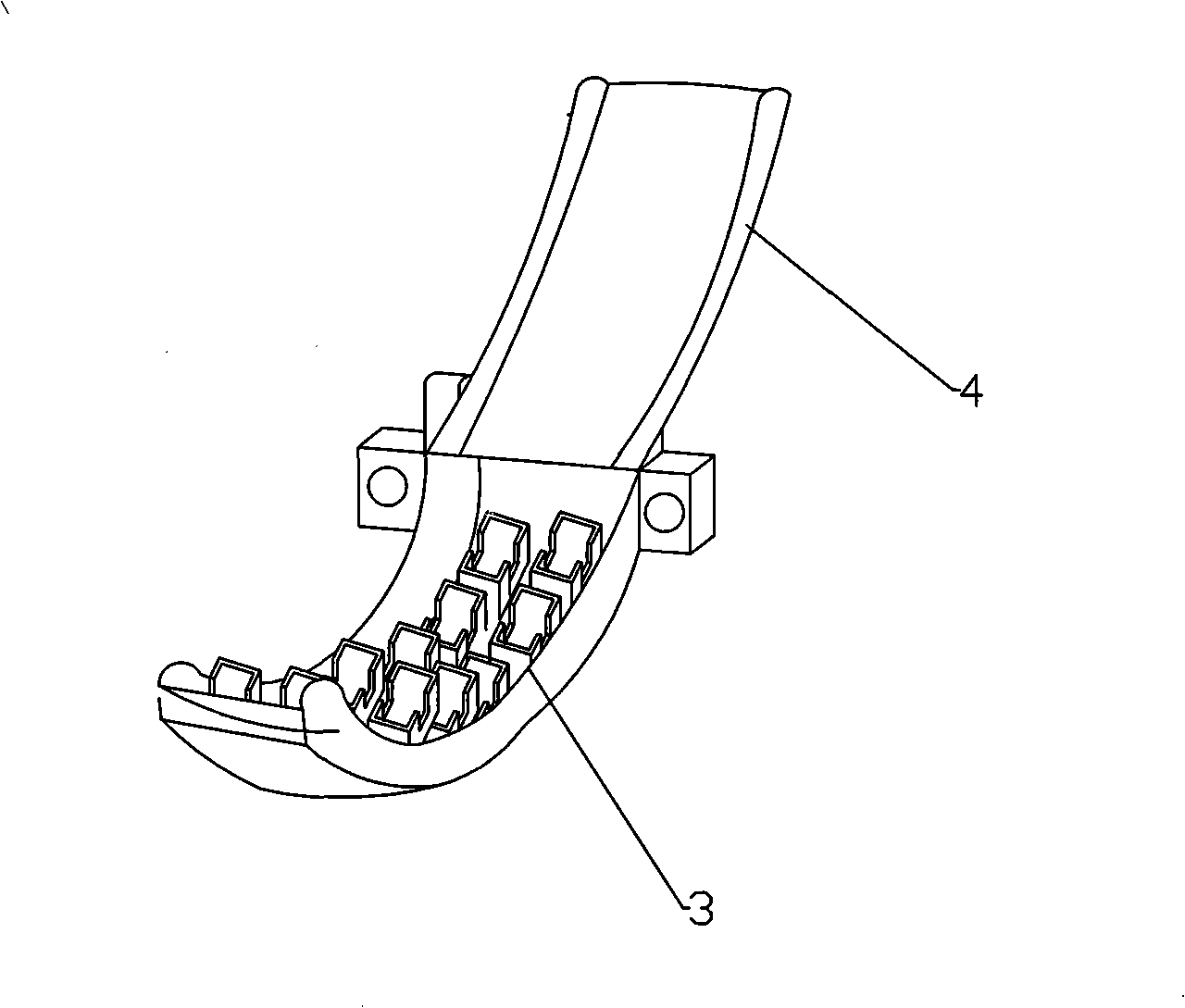
[0011] see Figure 1-2 : A wire drawing machine with a protective cover, including a body 1, a transmission mechanism, a wire drawing mechanism, a wire winding mechanism, a cooling lubricating device and an electrical control system, each group of wire drawing mechanisms includes two tower pulleys 2 and a mold base 3, the mold The frame 3 is arranged between the two tower pulleys 2, and the drawing die is installed on the mold frame 2; the protective cover 4 matched with the mold frame 2 is installed above the mold frame 2, and the protective cover 4 is connected with the mold frame 2. Between the frames 2 there are openings for the metal wires before and after passing through the mold to pass through, and the nozzles of the nozzles 5 of the cooling and lubricating device are aimed at the two cone wheels 2 on both sides of the mold frame.

[0012] By installing the pr...


PUM


Abstract

The invention relates to a wire-drawing machine with a protective cover. The machine comprises a machine body, a transmission mechanism, wire-drawing mechanisms, a wire winding mechanism, a cooling / lubricating device and an electrical control system. Each wire-drawing mechanism comprises two cone pulleys and a die holder, wherein the die holder is arranged between the two cone pulleys and provided thereon with a wire-drawing die. The machine further comprises the protective cover that is arranged above the die holder and engaged with the die holder. An opening is provided between the protective cover and the die holder to allow metal wires to pass through. Nozzles of the cooling / lubricating device are aligned oppositely to the cone pulleys. The inventive wire-drawing machine with the protective cover has low risks of wire breakage and fire hazard.

Description

(1) Technical field [0001] The invention relates to a wire drawing machine for drawing metal wire. (2) Background technology [0002] The existing wire drawing machine includes a fuselage, a transmission mechanism, a wire drawing mechanism, a wire winding mechanism, a cooling and lubricating device and an electrical control system, wherein the wire drawing mechanism can be one group or multiple groups, and each group of wire drawing mechanisms includes two towers The mold base is set between the two tower wheels in the same group, and the drawing die is installed on the mold base; the cooling and lubricating device usually uses an oil injection pipe. When working, the oil injection port of the oil injection pipe is aligned with the drawing die Spray to play the role of cooling and lubrication. However, the cooperation between the traditional wire drawing mechanism and the cooling and lubricating device also has the following defects: (1) The oil is viscous, and the residual...

Claims


Application Information

Patent Timeline
IPC IPC(8): B21C1/02B21C9/00A62C3/00
Inventor 周贤言
Owner 周贤言
Learn More