
Method for pressing tank-type bulkhead using three rollers rolling machine

A technology for pressing grooves and triggers, which is used in forming tools, manufacturing tools, metal processing equipment, etc., and can solve the problems of large pressing workload and splicing workload, long production cycle of ship trough bulkheads, and unsmooth butt joints, etc. problems, to achieve the effect of reducing the workload of pressing and splicing, reducing the number of vertical splicing, and speeding up the production cycle

Inactive Publication Date: 2010-11-03
江苏新扬子造船有限公司
View PDF8 Cites 2 Cited by
  • Summary
  • Abstract
  • Description
  • Claims
  • Application Information

AI Technical Summary

Problems solved by technology

[0003] 1. The size of the general trough bulkhead is about 20000mm×20000mm. Due to the limitation of the processing capacity of the hydraulic machine, it must be divided into many small pieces. The workload of pressing and splicing is very large. At the same time, a large number of splicing welds affect the appearance, and the production cost is high. Low production efficiency
[0004] 2. In fact, single-groove parts have machining errors allowed by the precision, but in the splicing process of many parts, errors will accumulate and cause the final error to exceed the standard or the notch butt joint is not smooth
Generally, this problem can only be eliminated by adding a butt trimming allowance for single-groove parts, resulting in material waste
[0005] 3. The size and accuracy of splicing are generally controlled by splicing tire frames in use for single-groove components, resulting in sluggish site and low utilization rate
[0006] Due to the above reasons, the production cycle of the corrugated bulkhead is long, the quality control is difficult, and the economy is not good.

Method used


Image

  • Method for pressing tank-type bulkhead using three rollers rolling machine
  • Method for pressing tank-type bulkhead using three rollers rolling machine
  • Method for pressing tank-type bulkhead using three rollers rolling machine

Examples


Embodiment Construction

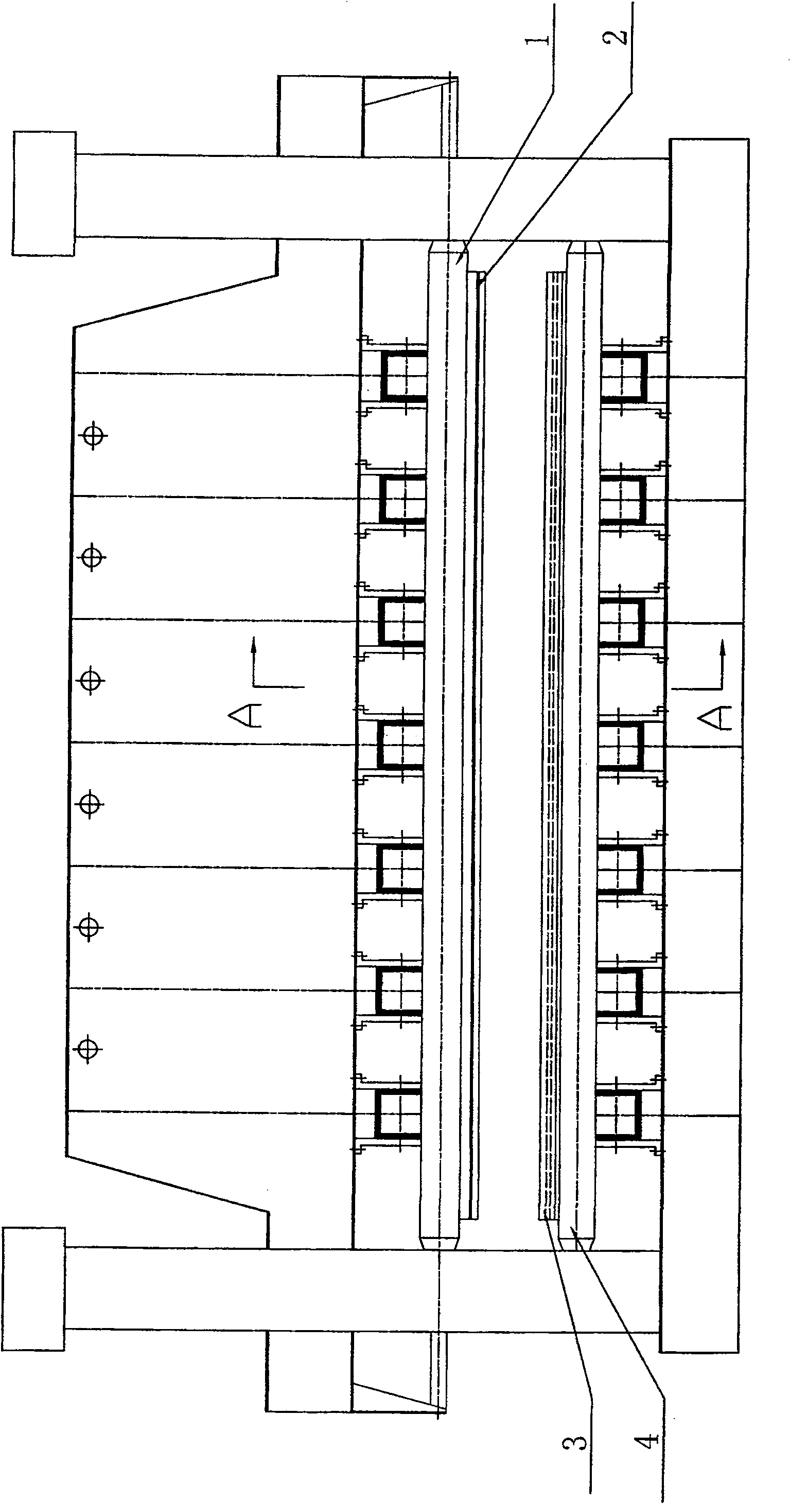
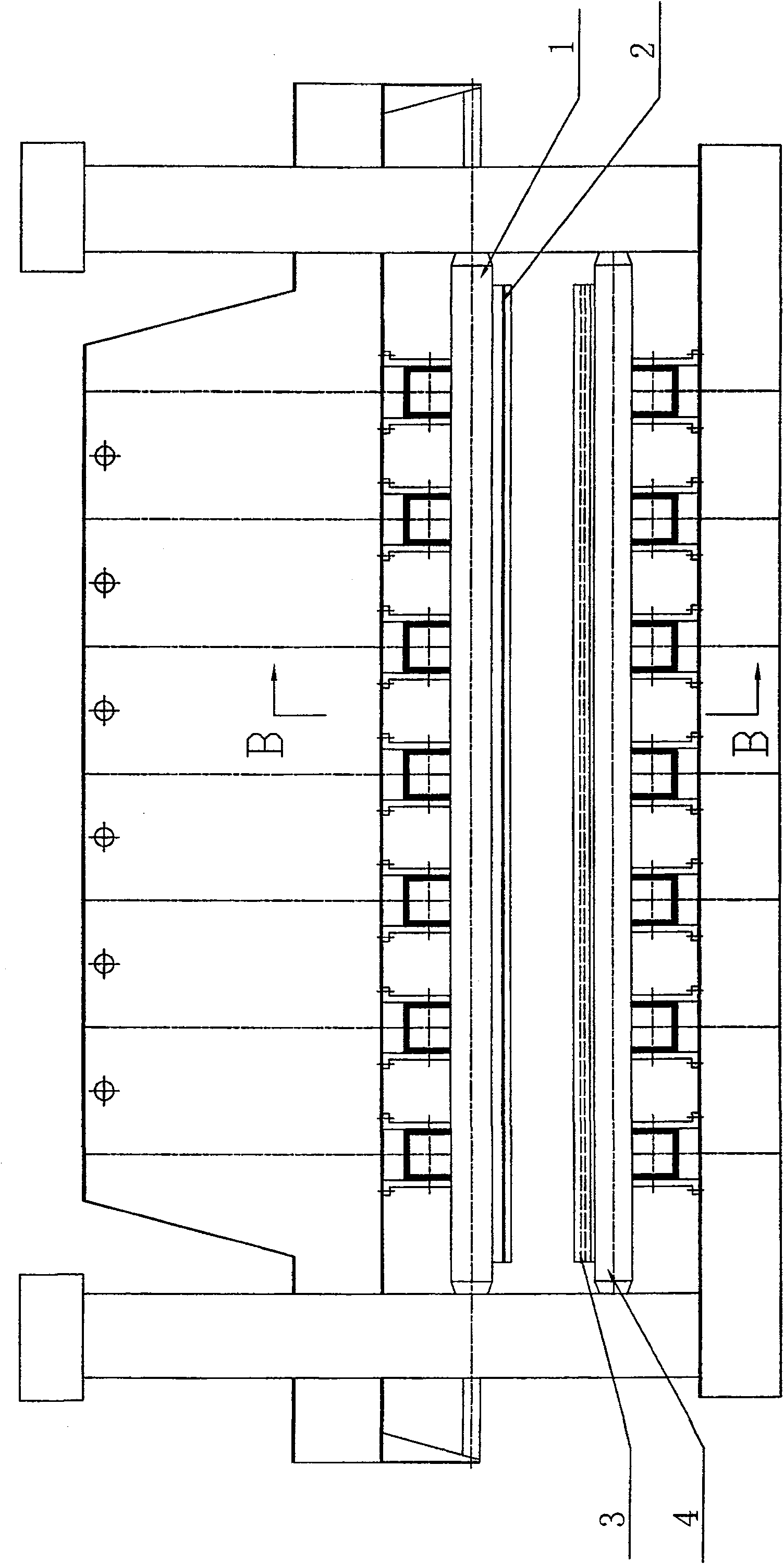
[0026] see figure 1 , the present invention discloses a method of using a three-roll plate rolling machine to press a grooved bulkhead during shipbuilding, the method comprising:

[0027] According to the diameter of the upper and lower rollers of the three-roller plate bending machine and the gap between the two lower rollers, the upper mold base 2.1 and the lower mold base 3.2 of the upper and lower molds of the mold and the rollers are designed; it is determined according to the effective working length of the three-roller plate bending machine The length of the mould; according to the size of the knuckle of the notch of the grooved bulkhead and the arc at the knuckle, the size of the upper die pressure head and the lower die groove 3.1 of the upper and lower dies is designed.

[0028] Connect and fix the upper mold and the upper roller 1 through the screw buckle, place the lower mold on the two lower rollers, and then drive the upper mold to run downward through the upper ...


PUM


Abstract

The invention relates to a method for pressing corrugated bulkhead by using a three-roller bending machine in hull construction process and a mold. The method comprises the following steps of: arranging and mechanically fixing lower pressing molds equivalent to the effective work length of lower rollers on two lower rollers of the three-roller bending machine by utilizing the prior configuration of the three-roller bending machine and the effective work length of the roller; arranging and mechanically fixing upper pressing molds equivalent to the effective work length of upper rollers on single upper roller of the three-roller bending machine; setting the length of a slot-shaped component according to the pressing lengths of the upper and the lower molds; loading board material; driving the upper mold by the upper roller of the three-roller bending machine, which is used as a lengthened oil pressure machine, to press-mold the corrugated component by one step through the mutual restriction of the upper and the lower molds. The inventive method can lengthen the process length of the corrugated component by only one three-roller bending machine which is equipped with the special mold, thereby reducing the number of the components. With reduced process and joint workloads, increased production efficiency and improved process precision, the shipbuilding cost is lowed.

Description

technical field [0001] The invention relates to a method and a mold for pressing a grooved bulkhead with a three-roll plate rolling machine in the hull building process. It belongs to the technical field of shipbuilding. Background technique [0002] In the process of hull construction, due to the design and ship type requirements of some ships (such as bulk carriers and oil tankers), the subdivided transverse walls of cargo holds are generally designed as grooves. General shipyards now use hydraulic presses to press the grooved bulkheads in pieces, and then splicing them into a whole. That is: according to the span between the hydraulic press head and the body, and taking into account the maximum pressing length of the controllable pressing precision, divide the grooved bulkhead into small pieces (generally the maximum is 1500mmX3000mm), and then use the mold to press into a single groove type After passing the inspection, the parts are finally spliced ​​into a whole on t...

Claims


Application Information

Patent Timeline
Patent Type & Authority Patents(China)
IPC IPC(8): B21D5/02B21D37/10B21D37/12B21D5/14
Inventor 萧闲张祖祥何越桥周科伟
Owner 江苏新扬子造船有限公司
Learn More